
Pipe washing method and pipe washing apparatus
Patent Information
- Authority / Receiving Office
- US · United States
- Current Assignee / Owner
- Publication Date
- 2006-03-28
- Estimated Expiration
- Not applicable · inactive patent
Smart Images
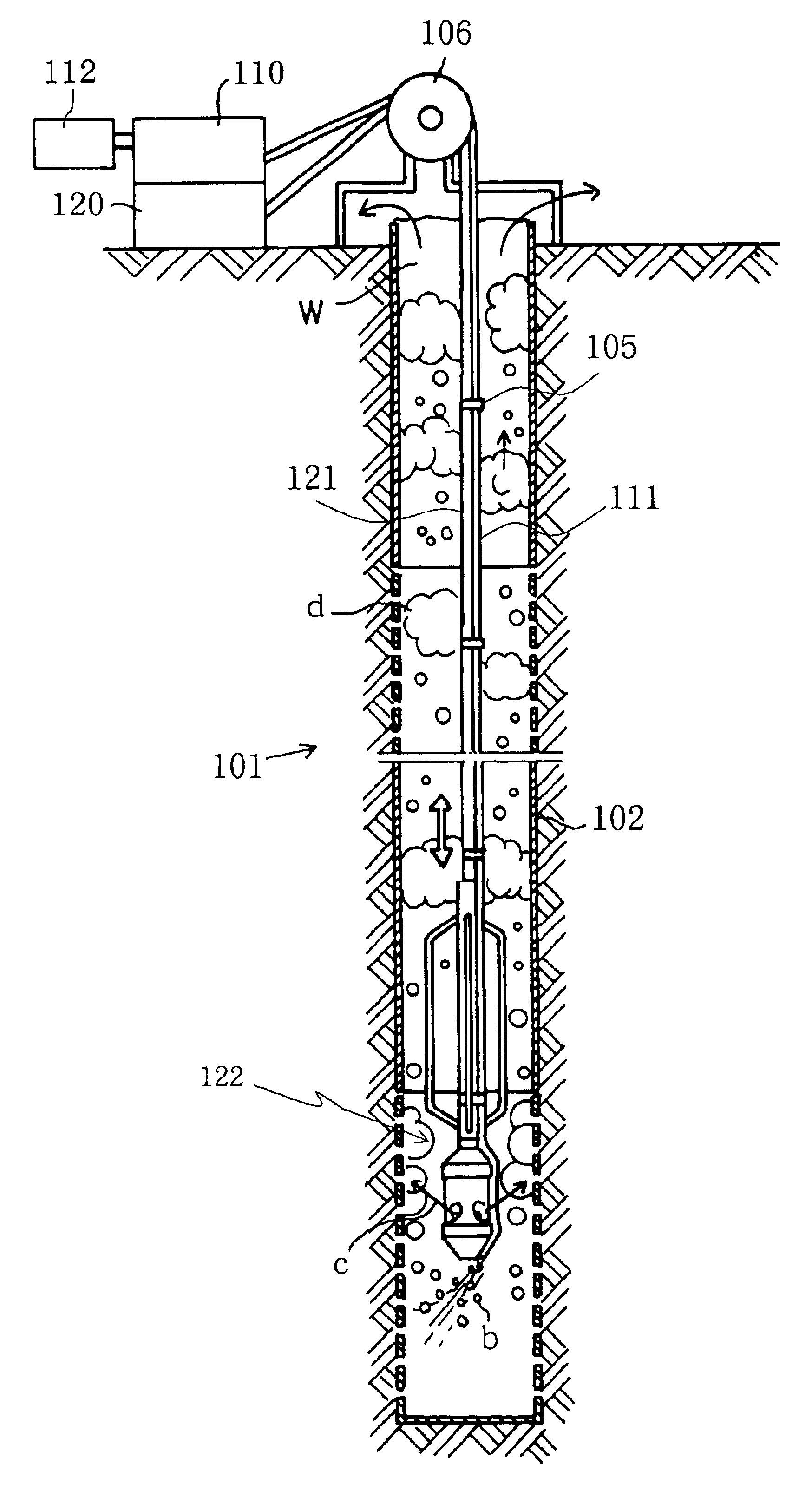
Figure 1 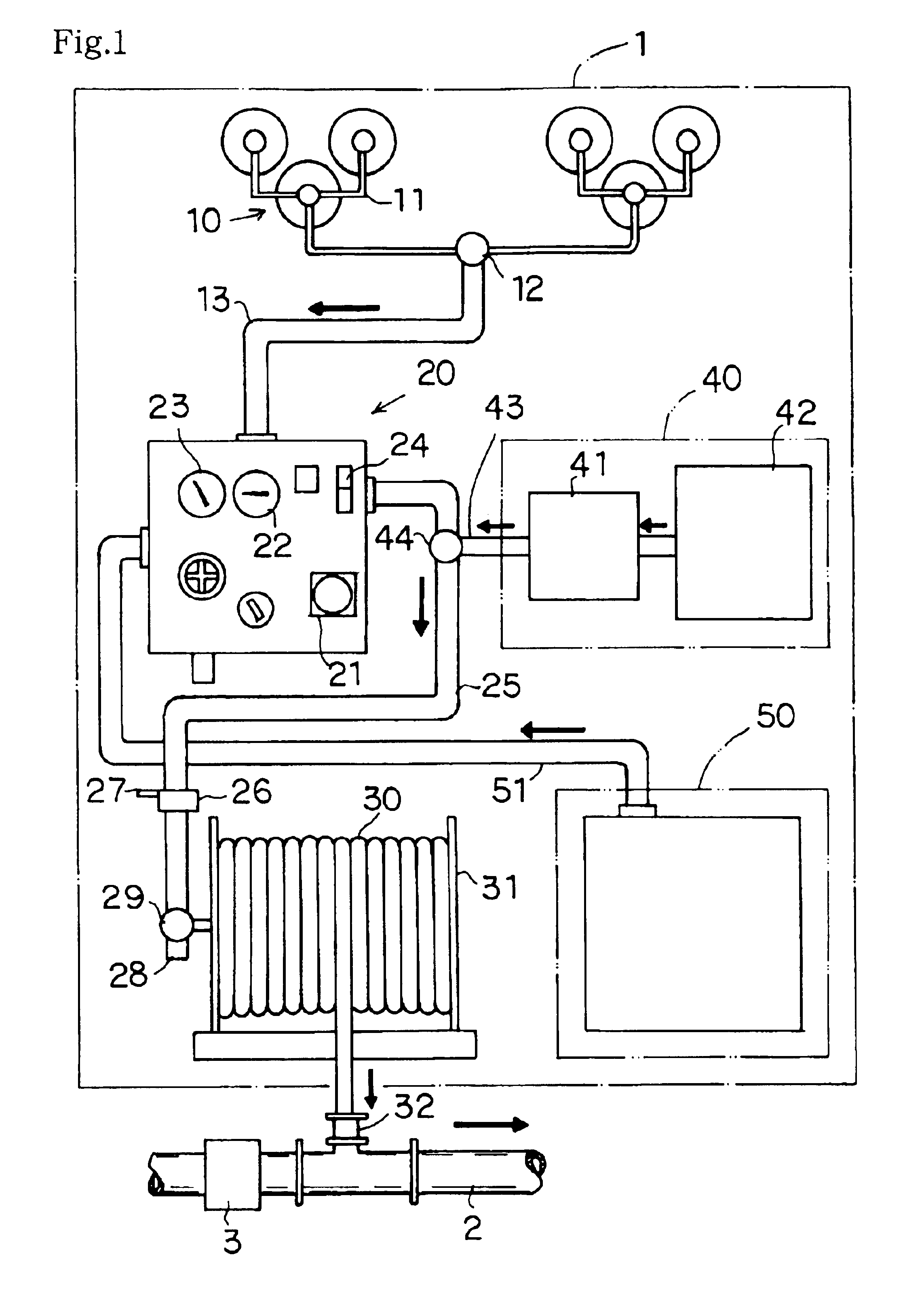
Figure 2 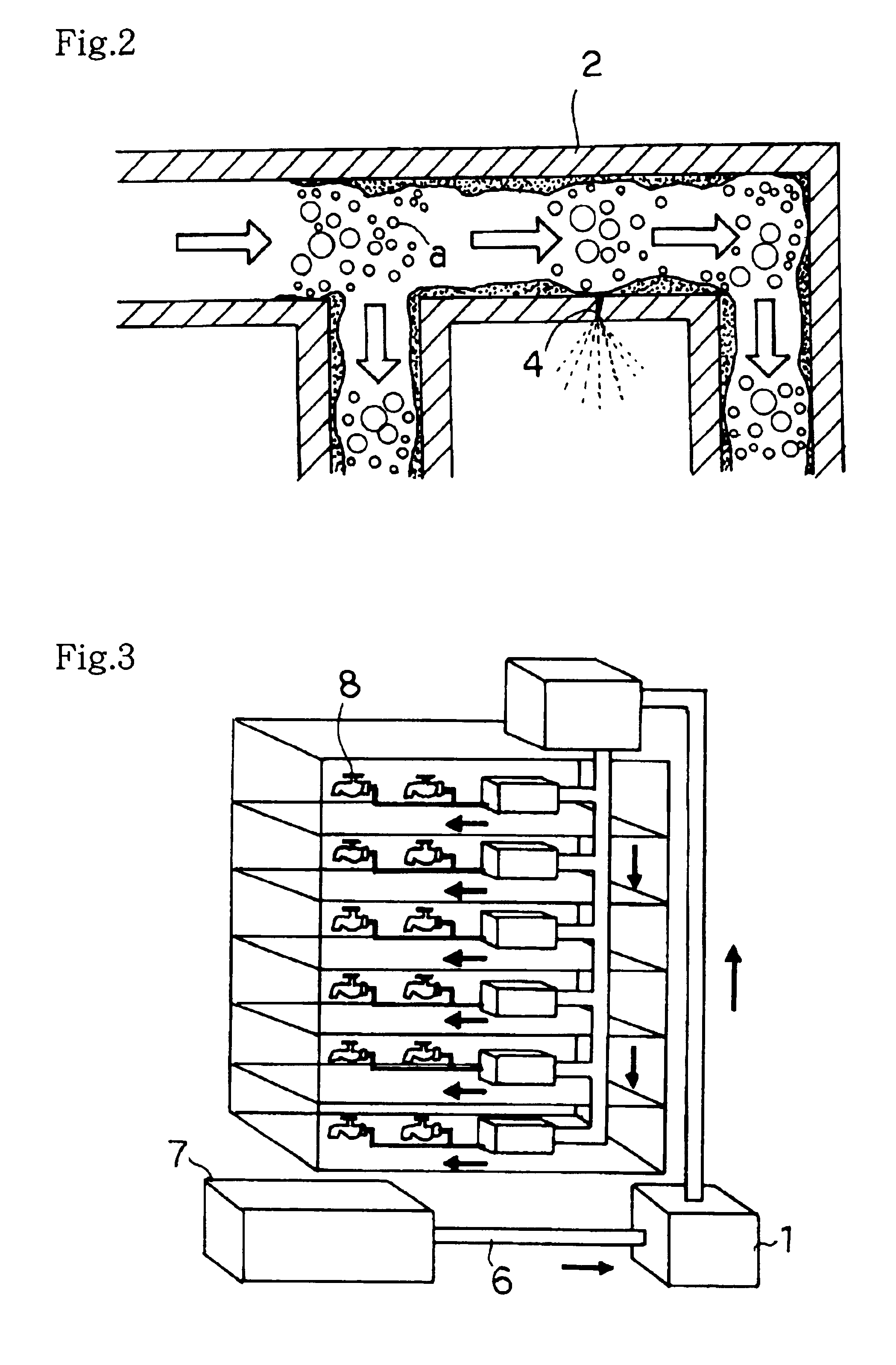
Figure 3
Abstract
Description
[0001] This application is the national phase under 35 U.S.C. § 371 of PCT International Application No. PCT / JP02 / 08682 which has an International filing date of Oct. 2, 2001, which designated the United States of America.TECHNICAL FIELD
[0002] The present invention relates to a pipe washing method and a pipe washing apparatus, and more particularly, to a pipe washing method and a pipe washing apparatus capable of effectively washing the interiors of pipes (water supply pipes and the like) of buildings, factories, and the like as well as capable of investigating water leakage in the pipes. Further, the present invention relates also to a well pipe washing method and a well pipe washing apparatus capable of effectively washing the interiors of well pipes for pumping up underground water in a short time.BACKGROUND ART
[0003] Usual buildings and complex housing have pipes (water supply pipes and the like) installed therein for supplying drinking water and water for other applications. Used ...
Examples
Embodiment Construction
[0033]Specific embodiments of the present invention will be described below in detail.
[0034]First, embodiments of a pipe washing method and a pipe washing apparatus of the present invention will be described. FIG. 1 is an overall schematic view showing an example of the pipe washing apparatus of the present invention.
[0035]The illustrated pipe washing apparatus 1 includes gas cylinders 10 filled with compressed carbon dioxide gas a, a dispersing device 20 capable of continuously or intermittently spouting the carbon dioxide gas a supplied from the gas cylinders 10, and a connection hose 30 for causing the dispersing device 20 to communicate with a pipe 2 to be washed.
[0036]A plurality of the gas cylinders 10 are coupled with each other through gas pipes 11 and connected to a gas hose 13 through an open / close valve 12. Further, an opposite end of the gas hose 13 is coupled with the dispersing device 20, and the carbon dioxide gas a in the gas cylinders 10 is supplied into the dispers...