
Thin film magnetic head, magnetic head device and magnetic recording/reproducing device
a magnetic head and magnetic recording technology, applied in the direction of metal sheet head, head with metal core, nanoinformatics, etc., can solve the problem of insufficient elimination of side fringe, and achieve the effect of removing recording blur
Patent Information
- Authority / Receiving Office
- US · United States
- Current Assignee / Owner
- Publication Date
- 2006-04-18
- Estimated Expiration
- Not applicable · inactive patent
Smart Images
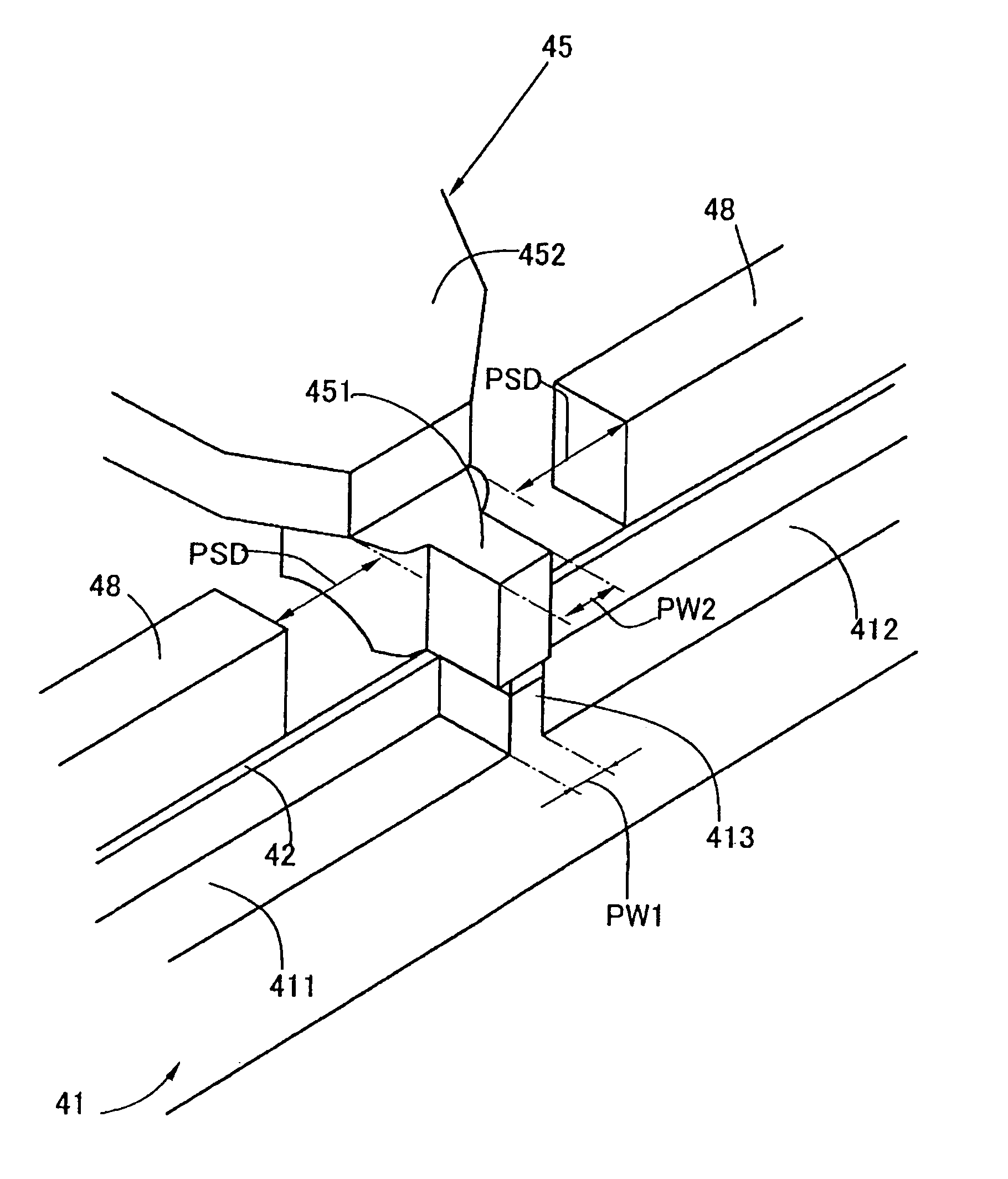
Figure 1 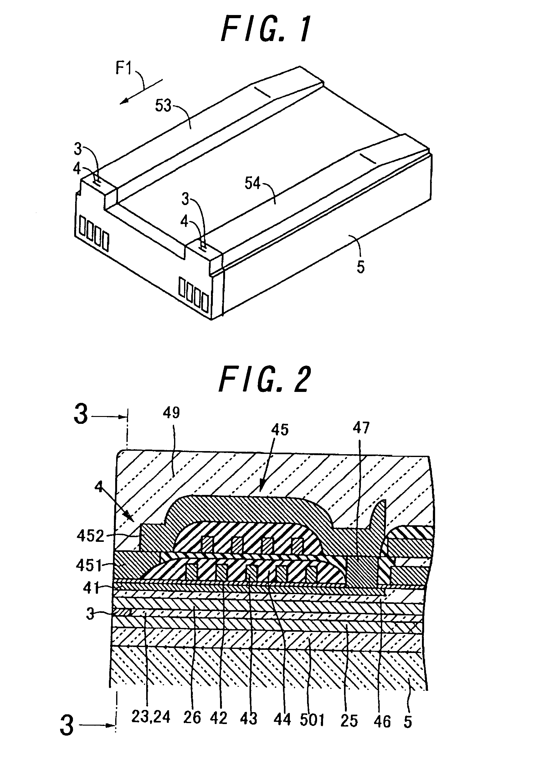
Figure 2 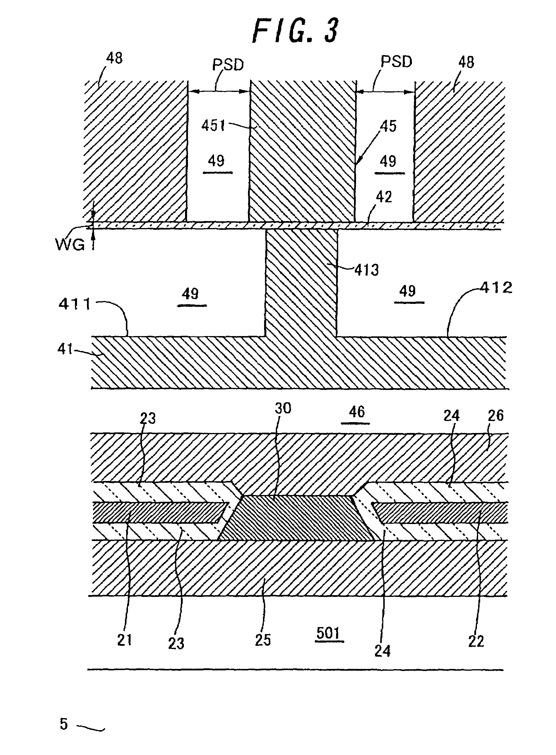
Figure 3
Abstract
Description
BACKGROUND OF THE INVENTION
[0001] 1. Field of the Invention
[0002] This invention relates to a thin film magnetic head, a magnetic head device and a magnetic recording / reproducing device.
[0003] 2. Related Art Statement
[0004] A composite type magnetic head comprised of a writing element and a reading element with a giant magnetoresistive effective film (hereinafter, called as a “GMR film”) is employed as a thin film magnetic head to be utilized in a magnetic disk drive device of a computer memory unit.
[0005] As the writing element is employed an inductive type electromagnetic conversion element, which is formed on the reading element. The inductive type electromagnetic conversion element is comprised of a bottom magnetic film, a top magnetic film, a coil film supported by a gap film and an insulating film and the like.
[0006] The forefronts of the bottom magnetic film and the top magnetic film are composed of a bottom pole piece and a top pole piece, respectively, which are opposed to each o...
Examples
Embodiment Construction
1. Thin Film Magnetic Head
[0039]FIG. 1 is a perspective view showing a thin film magnetic head according to the present invention, and FIG. 2 is an enlarged cross sectional view showing the thin film magnetic head in FIG. 1. FIG. 3 is an enlarged cross sectional view showing the thin film magnetic head in FIG. 2, taken on line “3—3”, and FIG. 4 is an enlarged plan view showing the writing element of the thin film magnetic head in FIGS. 1–3, and FIG. 5 is an enlarged perspective view showing the pole portions of the thin film magnetic head in FIGS. 1–4. In this embodiment, a composite type thin film magnetic head, comprised of a writing element 4 and a reading element 3, is shown. The writing element 4 and the reading element 3 are formed on a base 5 to be employed as a slider, and the forefronts of the elements 3 and 4 are located at the air bearing surfaces (hereinafter, called as “ABS”s) 53 and 54 of the thin film magnetic head, respectively, which are opposite to a magnetic recor...