
Deployment device for a fin
a technology of deployment device and fin, which is applied in the direction of self-propelled projectiles, transportation and packaging, weapons, etc., can solve the problems of limited use of such a mechanism, high cost of motors, and large volume inside the projectile, and achieve quick and reliable deployment of fins, reduce the intrusion of fins in the projectile, and reduce the effect of cos
Patent Information
- Authority / Receiving Office
- US · United States
- Patent Type
- Patents(United States)
- Current Assignee / Owner
- Publication Date
- 2006-06-13
Smart Images
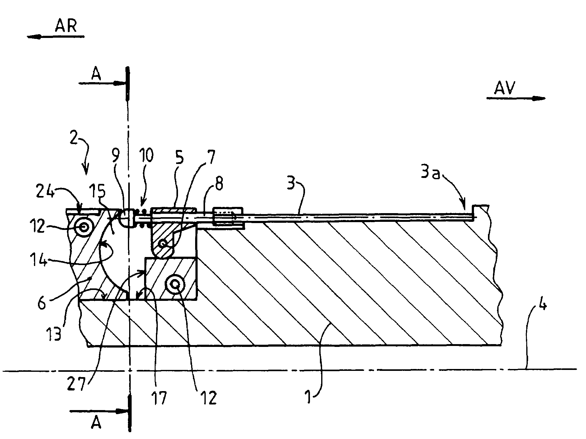
Figure 1 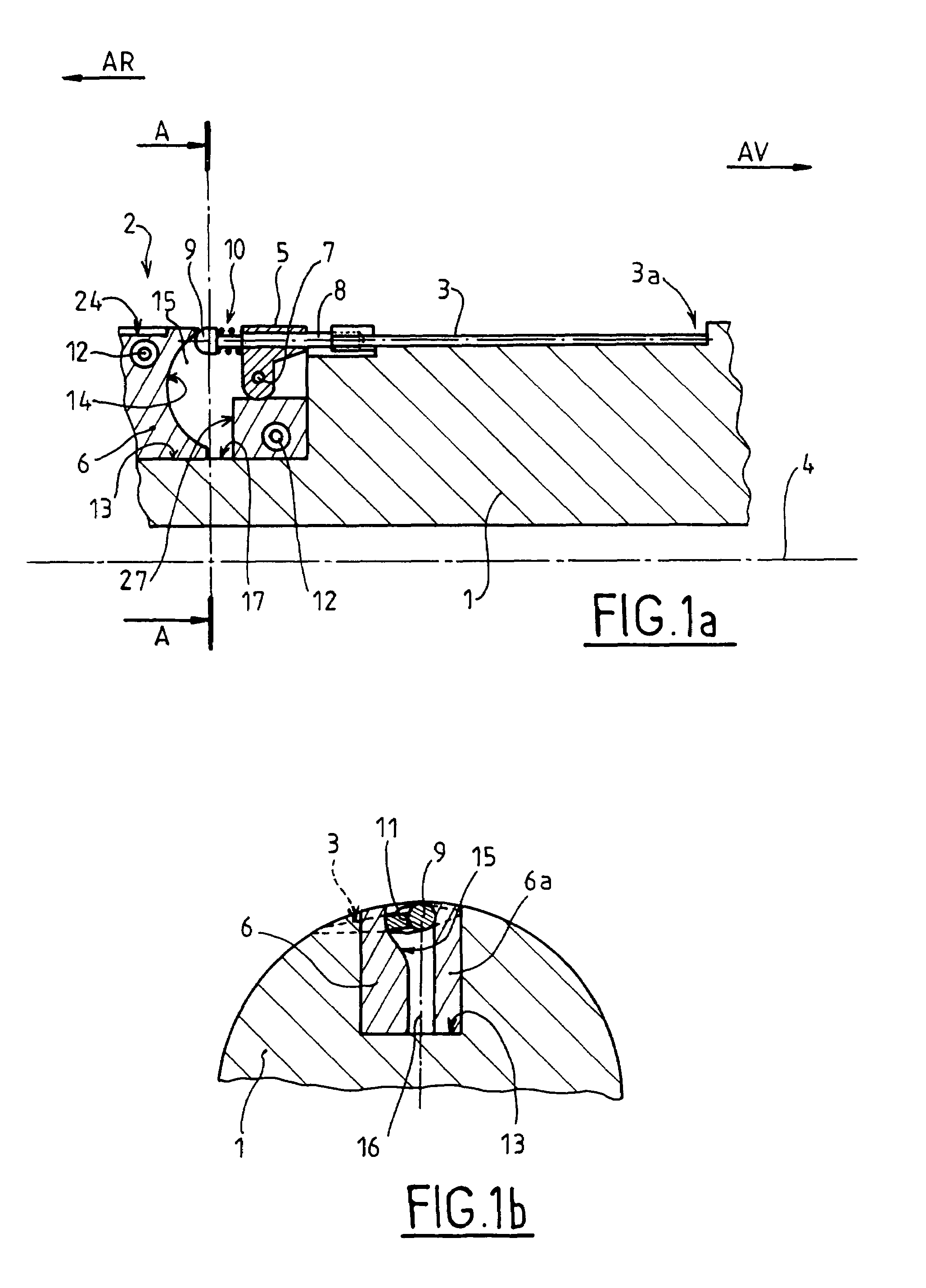
Figure 2 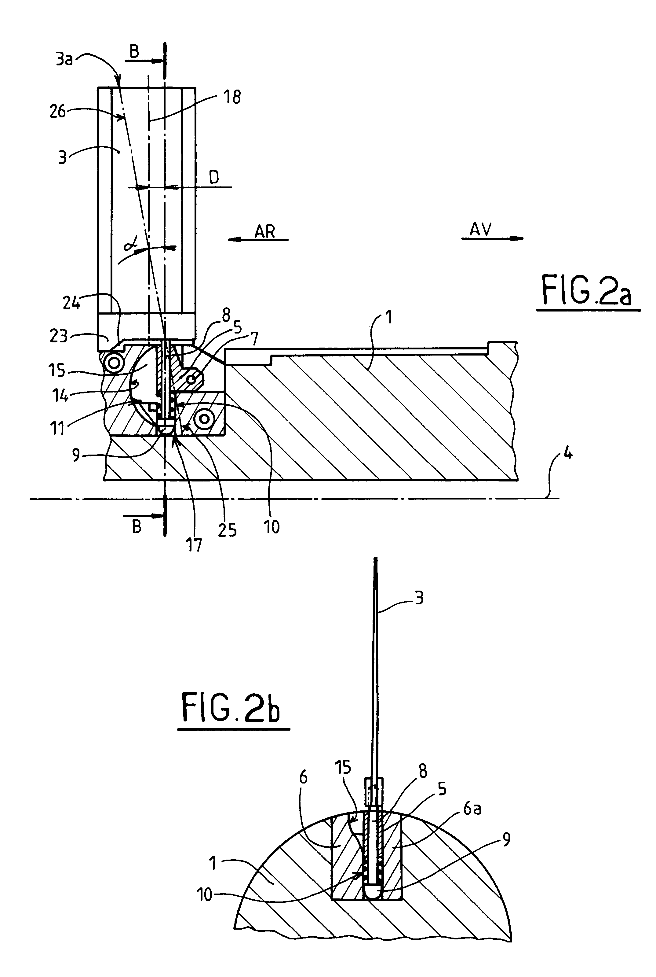
Figure 3
Abstract
Description
BACKGROUND OF THE INVENTION
[0001] 1. Field of the Invention
[0002] The technical scope of the invention is that of deployable fins fitted onto projectiles.
[0003] 2. Description of the Related Art
[0004] Projectile fins generally have a stabilizing role. They are grouped at a rear part of the projectile to form a tailpiece.
[0005] Certain projectiles have other fins whose role is that of guidance. These fins are generally placed at the front part of the projectile.
[0006] For reasons of their overall bulk and so as to enable firing from a gun barrel, the fins must be folded either backwards or forwards along the projectile, or inside it, before firing.
[0007] They must deploy upon exiting the gun barrel to ensure fulfill their stabilizing or guidance role.
[0008] Different solutions have been proposed to ensure this deployment function.
[0009] Patent FR2623898 thus describes a deployment device in which the fins are organized along an external wall of the projectile. Each fin is firstly driven by a ...
Examples
Embodiment Construction
[0030]FIG. 1a shows a partial longitudinal section of a rear part of a projectile 1. The section is made at a deployment device 2 for a stabilizing fin 3. The projectile is generally fitted with 3 to 8 identical stabilizing fins which all have identical deployment devices.
[0031]Here, the fin 3 is folded along the projectile body 1. The plane of the fin is thus positioned along a projectile wall and is oriented substantially in parallel to the axis 4 of the projectile.
[0032]The external end 3a of the fin is oriented towards the front part (reference AV) of the projectile, and a shearable retention device (such as a polyamide ring, not shown) will be advantageously provided at this extern end 3a.
[0033]The external end 3a of the fin may receive an additional device allowing the opening of the fin to be started by the effect of the aerodynamic flow, for example a detachable blade. Such a blade forms the subject of patent FR2721702. It is thus unnecessary to describe it in further detai...