
Ball-and-socket joint
a ball-and-socket joint technology, applied in the direction of pivots, shafts and bearings, couplings, etc., can solve the problems of premature wear of joints, and achieve the effect of reducing the requirements of dimensional tolerances affecting the service li
Patent Information
- Authority / Receiving Office
- US · United States
- Patent Type
- Patents(United States)
- Current Assignee / Owner
- Publication Date
- 2008-04-15
- Estimated Expiration
- Not applicable · inactive patent
Smart Images
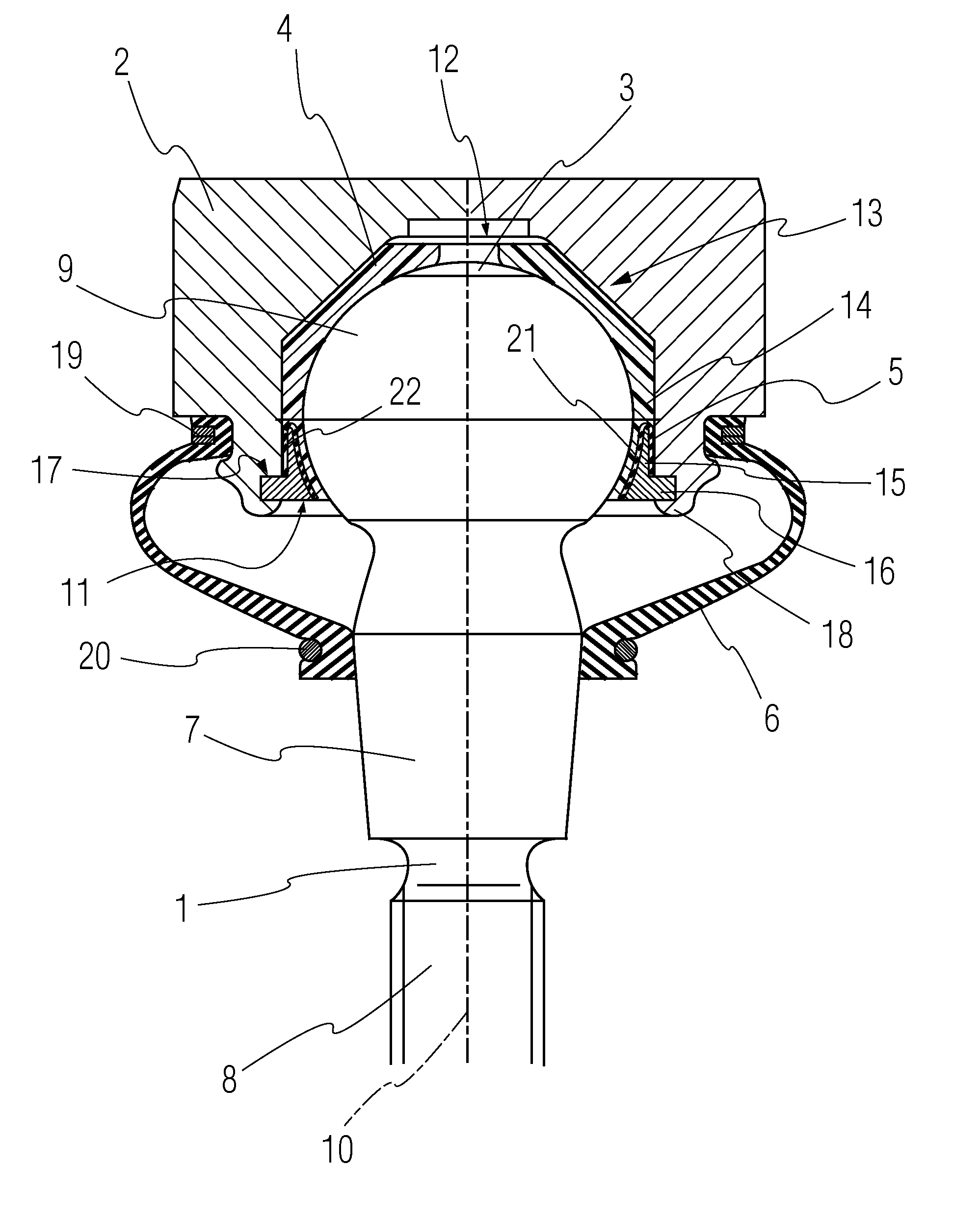
Figure 1 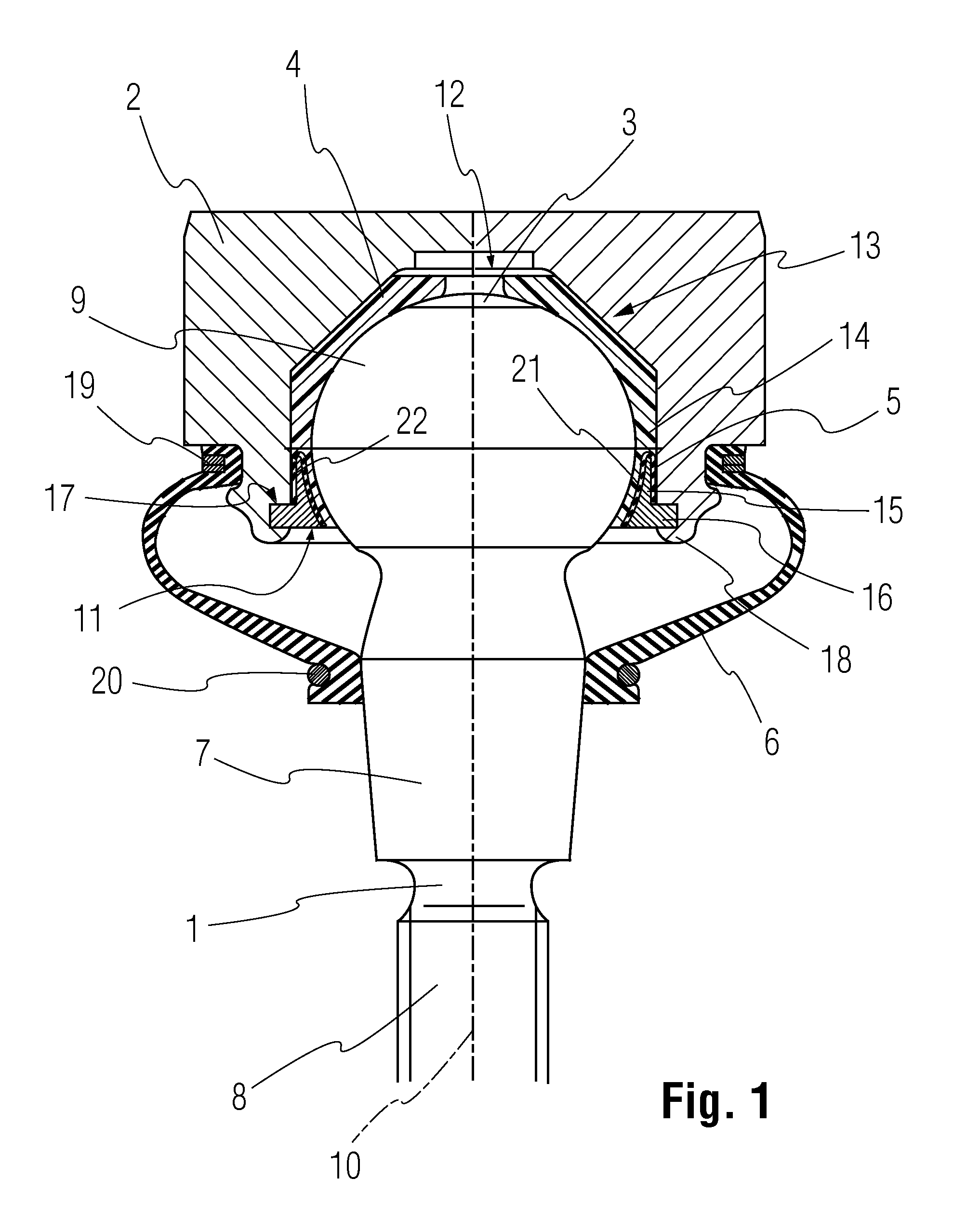
Figure 2 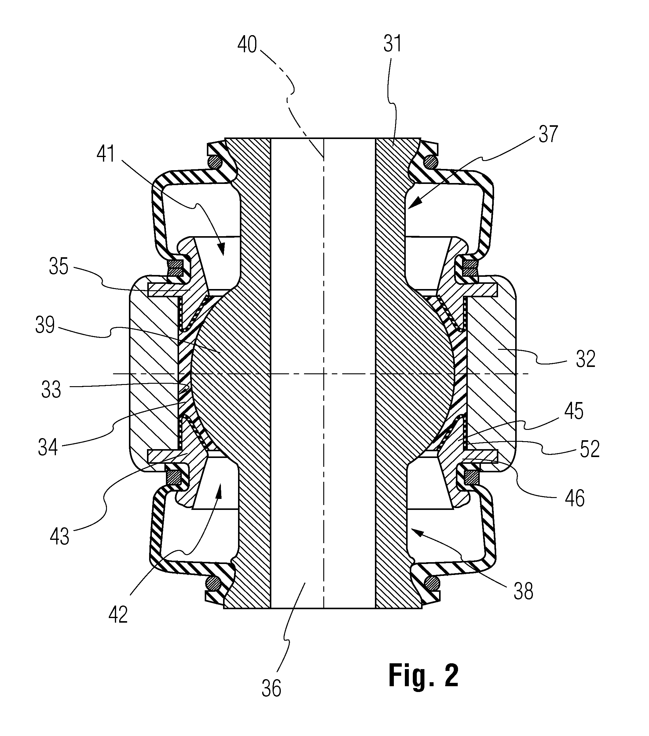
Figure 3
Abstract
Description
FIELD OF THE INVENTION
[0001] The present invention pertains to a ball-and-socket joint with a pivot pin, which is accommodated rotatably and tiltably with a spherical joint area in a bearing shell, which is in turn arranged in the recess of a joint housing, wherein a closing ring fixes the bearing shell in the joint housing in the axial longitudinal direction of the pivot pin by at least one contact surface.BACKGROUND OF THE INVENTION
[0002] Various different designs of ball-and-socket joints of the type described in the introduction have been known from the state of the art, and they are used, in particular, in vehicles and steering mechanisms of passenger cars and utility vehicles. A decisive criterion for the quality of the ball-and-socket joints used is their service life, which should be sufficiently long under difficult stress conditions. An essential requirement for ensuring a sufficient service life is the narrowest possible tolerances of the ball-and-socket joint components, a...
Examples
Embodiment Construction
[0017]Referring to the drawings in particular, FIG. 1 shows a ball-and-socket joint, which comprises essentially a pivot pin 1, a joint housing 2, a one-part or multipart bearing shell 4 arranged within a recess 3 of the joint housing 2, a closing ring 5 as well as a sealing bellows 6 consisting of an elastic material. Such a ball-and-socket joint may be used, e.g., in motor vehicles and specifically in the chassis or on steering mechanism parts of passenger cars and utility vehicles. It is used to make possible a controlled rotary and tilting movement between two components, wherein the pivot pin with its free end projecting from the joint housing, which has a cone 7 and a threaded fastening end 8 joining the cone is fixed at a motor vehicle component. The other, movable component corresponding to this is fixed to the joint housing 2 with fastening means not specifically shown here. At the end located opposite the fastening end 8, the pivot pin 1 has a spherical joint area 9, which...