
Method and system of dynamic power cutoff for active leakage reduction in circuits
a technology of active leakage and circuit, applied in the direction of power consumption reduction, pulse technique, instruments, etc., can solve the problems of long sleep period, data loss, and reduced circuit leakage power in standby mode, so as to reduce active leakage
Patent Information
- Authority / Receiving Office
- US · United States
- Patent Type
- Patents(United States)
- Current Assignee / Owner
- Publication Date
- 2010-10-05
- Estimated Expiration
- Not applicable · inactive patent
Smart Images
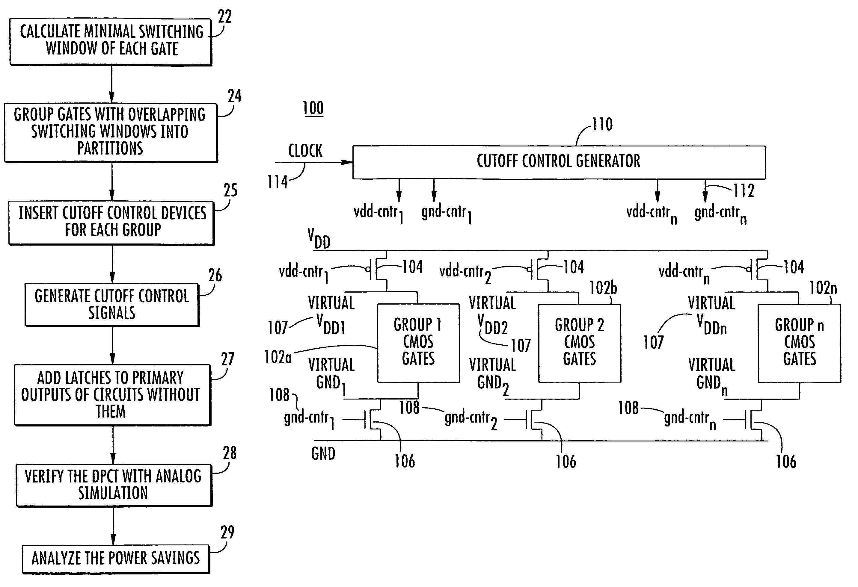
Figure 1 
Figure 2 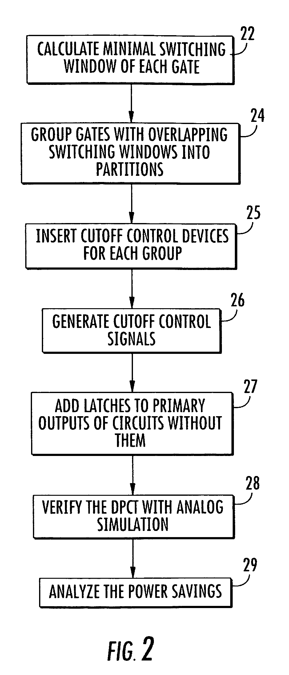
Figure 3
Abstract
Description
CROSS REFERENCE TO RELATED APPLICATION
[0001] This application claims the benefit of U.S. Provisional Patent Application No. 60 / 849,539, filed Oct. 4, 2006, the entirety of which is hereby incorporated by reference into this application.BACKGROUND OF THE INVENTION
[0002] 1. Field of the Invention
[0003] The present invention relates to reducing active leakage power in computer hardware and in particular to a method and system for active leakage power reduction in circuits using a dynamic power cutoff technique.
[0004] 2. Description of Related Art
[0005] Leakage power is increasingly significant in CMOS circuits due to the exponential increase of subthreshold and gate leakage currents from technology scaling. Leakage power is becoming a major fraction of total VLSI chip power in active mode. Conventional leakage reduction techniques have been proposed. A forced stacking method reduces leakage power by inserting an extra serially connected transistor in the gate pulldown or pullup path and tur...
Examples
Embodiment Construction
[0020]Reference will now be made in greater detail to a preferred embodiment of the invention, an example of which is illustrated in the accompanying drawings. Wherever possible, the same reference numerals will be used throughout the drawings and the description to refer to the same or like parts.
[0021]FIG. 2 is a flow diagram of a method for dynamic power cutoff for active leakage reduction in a circuit 20 in accordance with the teachings of the present invention. In block 22, a minimal switching window (MSW) for each gate is identified. In one embodiment, static timing analysis can be used to determine the minimal switching window (MSW).
[0022]The switching window and minimal switching window (MSW) of a gate are based on a timing window, as shown in FIG. 3. The timing window can be conventional as described in T. Raja, V. Agrawal, and M. Bushnell, “CMOS Circuit Design for Minimum Dynamic Power and Highest Speed,” in Proc. of the 17th Int'l. Conf on VLSI Design, pp. 1035-1040, Janu...