
Collecting chamber for a cleaning appliance
a collection chamber and cleaning technology, applied in the direction of cleaning equipment, cleaning filter means, suction filters, etc., can solve the problems of affecting the performance of the cleaning appliance, unwanted spillage of dirt and dust, etc., and achieve the effect of simple and convenient manufactur
Patent Information
- Authority / Receiving Office
- US · United States
- Patent Type
- Patents(United States)
- Current Assignee / Owner
- Publication Date
- 2011-08-16
Smart Images

Figure 1 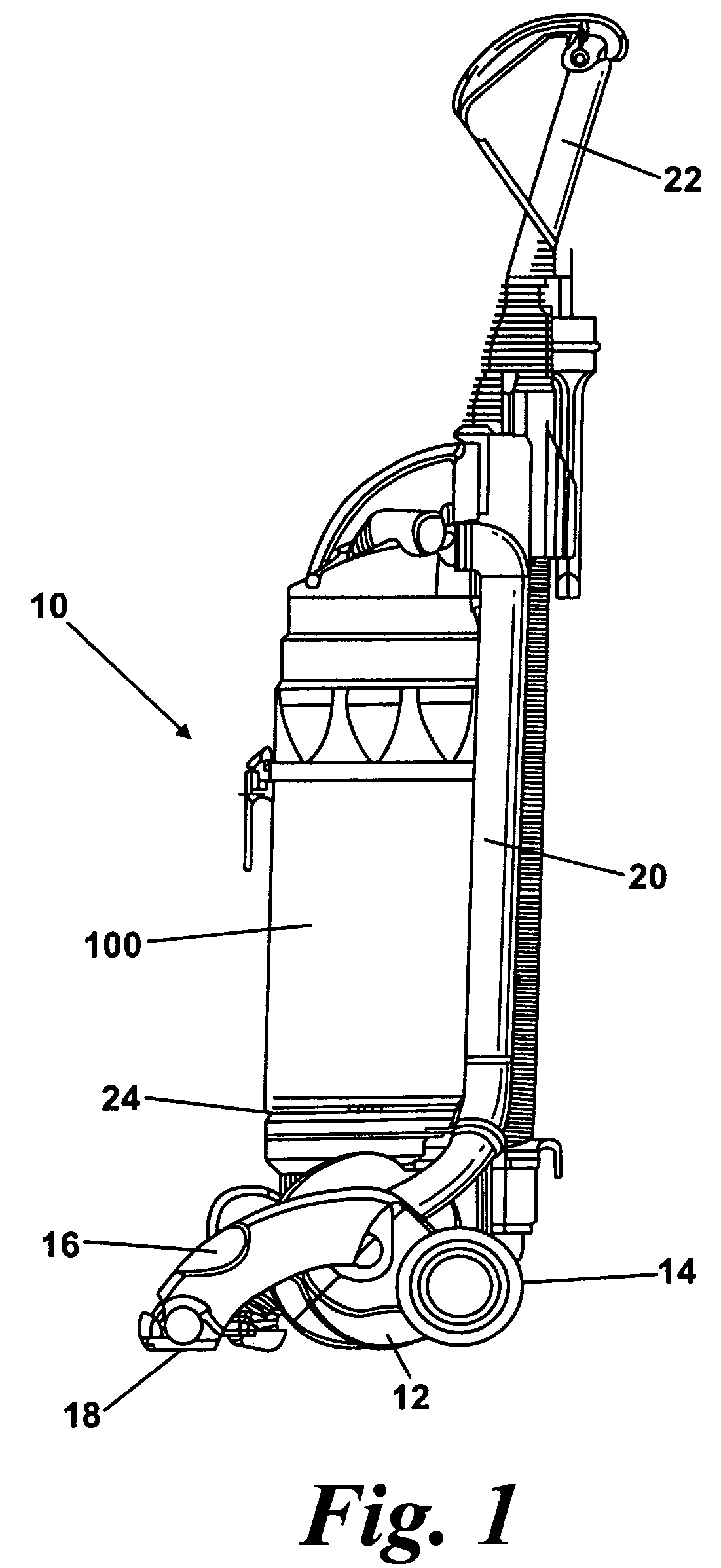
Figure 2 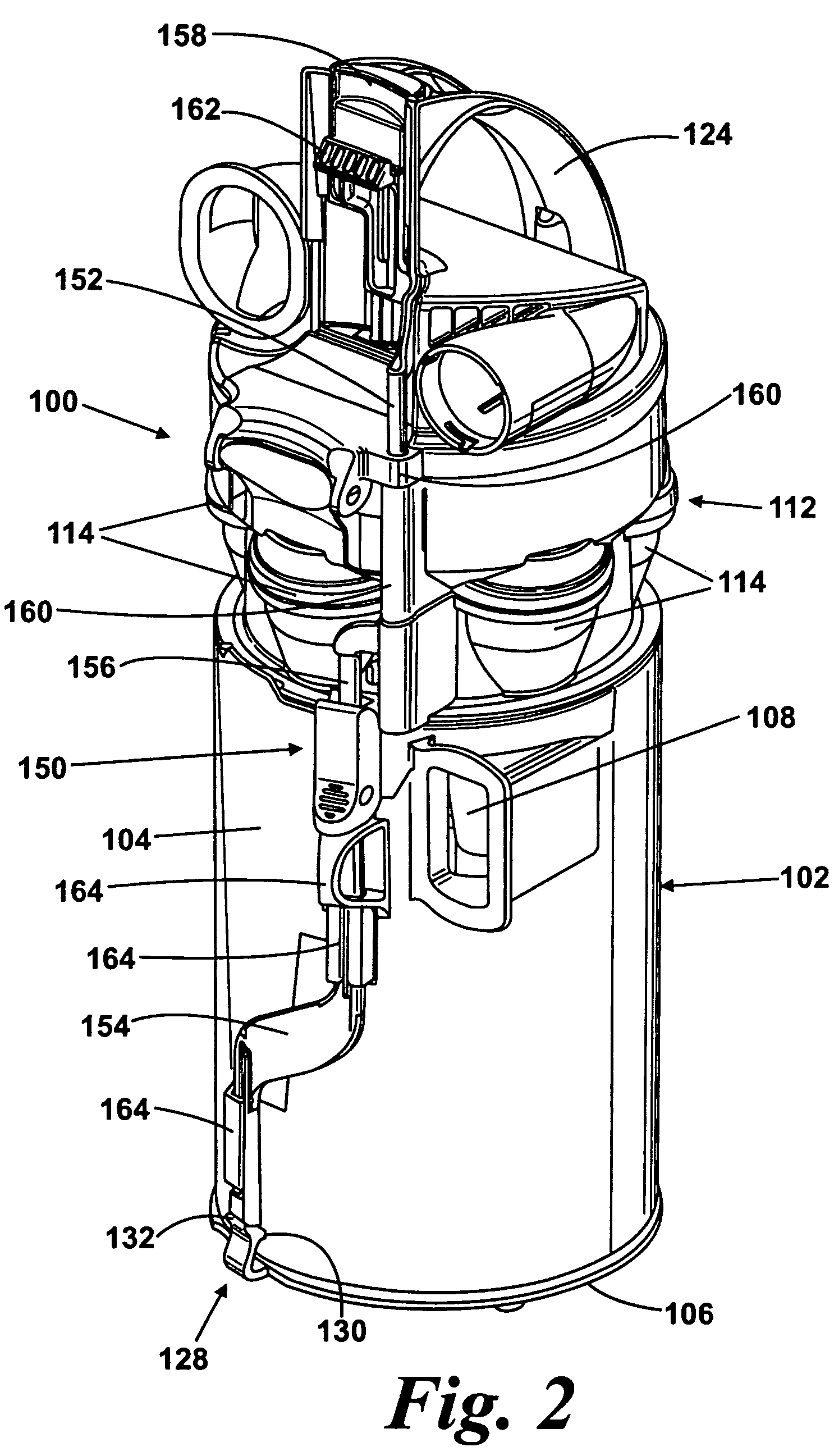
Figure 3
Abstract
Description
REFERENCE TO RELATED APPLICATIONS
[0001] This application claims the priority of United Kingdom Application No. 0708536.8, filed May 3, 2007, the contents of which are incorporated herein by reference.FIELD OF THE INVENTION
[0002] The present invention relates to a collecting chamber for a cleaning appliance. Particularly, but not exclusively, the present invention relates to a collecting chamber for a vacuum cleaner.BACKGROUND OF THE INVENTION
[0003] Vacuum cleaners which utilise cyclonic separators are well known. Examples of such vacuum cleaners are shown in EP 0 042 723, EP 1 370 173 and EP 1 268 076. In general, an airflow in which dirt and dust is entrained enters a first cyclonic separator via a tangential inlet which causes the airflow to follow a spiral or helical path within a collecting chamber so that the dirt and dust is separated from the airflow. Relatively clean air passes out of the chamber whilst the separated dirt and dust is collected therein. In some applications, and...
Examples
Embodiment Construction
[0022]FIG. 1 shows an upright vacuum cleaner 10 having a main body 12 which includes a motor and fan unit (not shown) and a pair of wheels 14. A cleaner head 16 is pivotably mounted on the lower end of the main body 12 and a dirty air inlet 18 is provided in the underside of the cleaner head 16 facing the floor surface. The main body 12 further includes a spine 20 which extends vertically upward and merges into a handle 22. The handle 22 can be manipulated by a user to manoeuvre the vacuum cleaner 10 across a floor surface. The main body 12 further includes a plurality of outlet ports 24 for exhausting air from the vacuum cleaner 10.
[0023]A collecting chamber 100 is releasably held on the main body 12. The collecting chamber 100 is supported on the main body 12 above the outlet ports 24 and lies adjacent the spine 20. The interior of the collecting chamber 100 is in communication with the dirty air inlet 18 through ducting in the spine 20. The collecting chamber 100 can be removed f...