
Drive apparatus for a vacuum fluorescent display
a technology of vacuum fluorescent display and drive circuit, which is applied in the direction of electric variable regulation, process and machine control, instruments, etc., can solve the problems of inconvenient separate supply of power to filament and other electrical loads, waste of power dissipation in the voltage dropper device, etc., and achieve the effect of reducing the power dissipation of the shunt voltage regulator and avoiding the cost of providing additional voltage regulators for other electrical loads
Patent Information
- Authority / Receiving Office
- US · United States
- Patent Type
- Patents(United States)
- Current Assignee / Owner
- Publication Date
- 2011-08-23
Smart Images
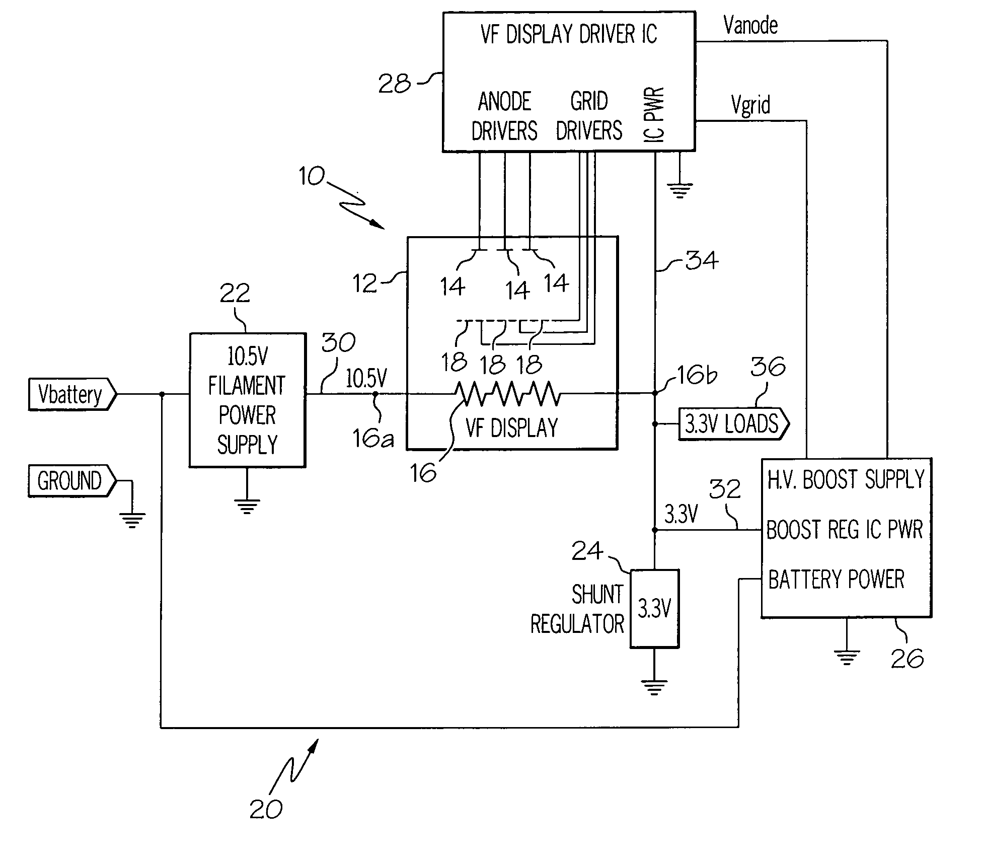
Figure 1 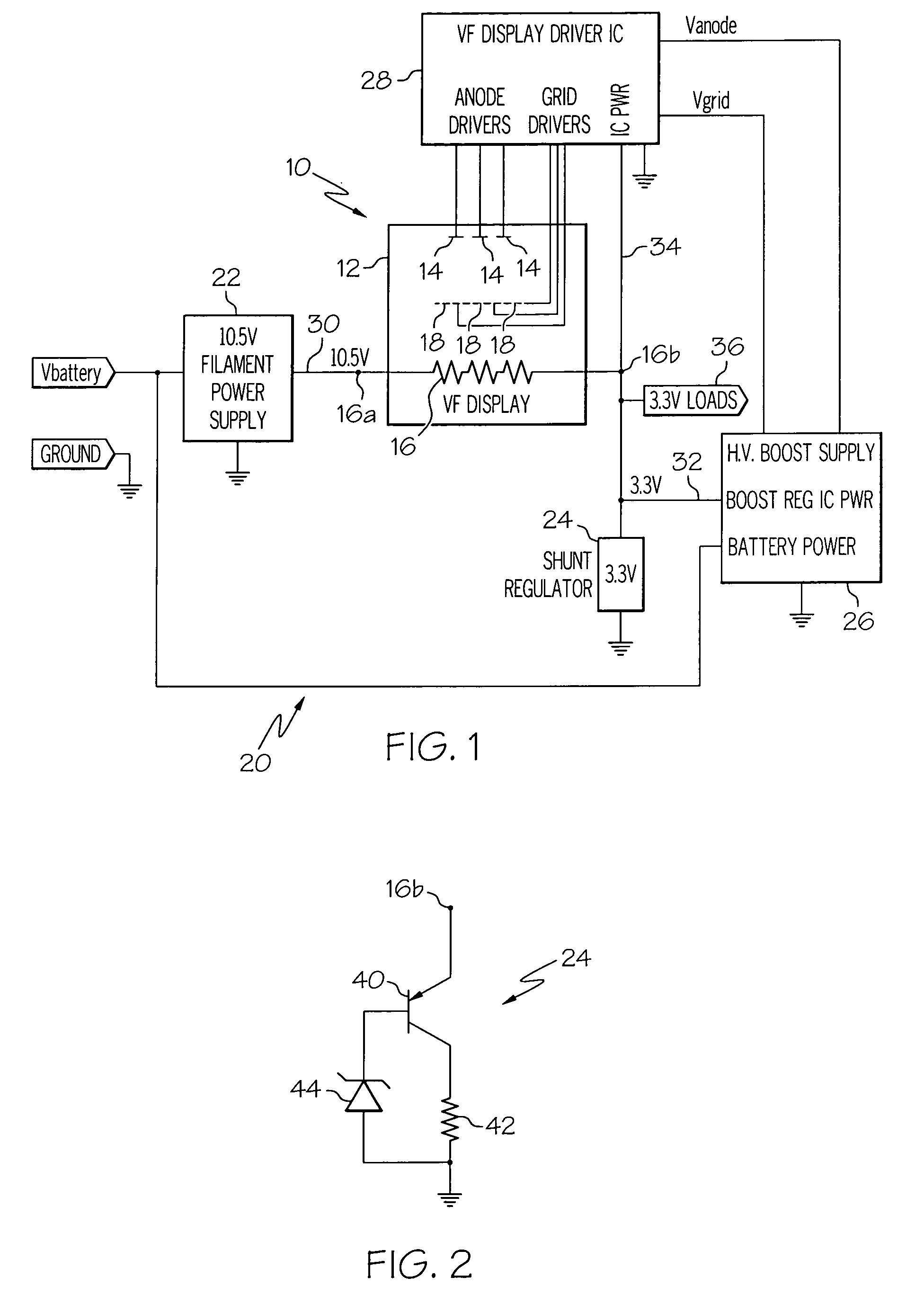
Figure 2
Abstract
Description
TECHNICAL FIELD
[0001] The present invention relates to an efficient and low-cost drive circuit for a vacuum fluorescent display (VFD).BACKGROUND OF THE INVENTION
[0002] Vacuum fluorescent displays (VFDs) are typically manufactured in the form of a glass housing having an evacuated central cavity containing phosphored anode segments arranged in a suitable display pattern, a filament (cathode), and a grid disposed between the filament and the anode segments. The filament is electrically heated to generate a cloud of electrons, and selected anode segments are illuminated when positive voltages are supplied to the grid and the selected anode segments. And to turn off the display, the grid is held at a negative potential with respect to the filament.
[0003] In applications where a single DC voltage source is used to drive a VFD, one end of the filament can be coupled to the source voltage, with the other end of the filament being coupled to ground potential (i.e., the negative terminal of the...
Examples
Embodiment Construction
[0008]The drive apparatus of the present invention is disclosed herein in the context of an instrument panel display powered from the storage battery of a motor vehicle, but it should be understood that the disclosed drive apparatus is equally applicable to other vehicular and non-vehicular applications.
[0009]Referring to FIG. 1, the reference numeral 10 generally designates a conventional VFD including an evacuated glass housing 12, a number of phosphored anode segments 14, a filament or cathode 16, and a number of grid segments 18 disposed between the filament 16 and the anode segments 14. In general, the display 10 is activated by passing electrical current through the filament 16 to generate a localized cloud of electrons, and supplying positive voltages to selected anode and grid segments 14, 18 to drive the electrons into the selected anode segments. To prevent anode illumination, the respective grid segments 18 are held at a voltage potential that is negative with respect to ...