
Human body supporting structure, particularly bicycle saddle and method of making same
a human body and supporting structure technology, applied in the field of sport and leisure, can solve the problems of poor cost-effectiveness, excessive weight of final product, and difficult implementation of methods, and achieve the effect of high efficiency and cost-effectiveness
Patent Information
- Authority / Receiving Office
- US · United States
- Patent Type
- Patents(United States)
- Current Assignee / Owner
- Publication Date
- 2012-03-06
Smart Images
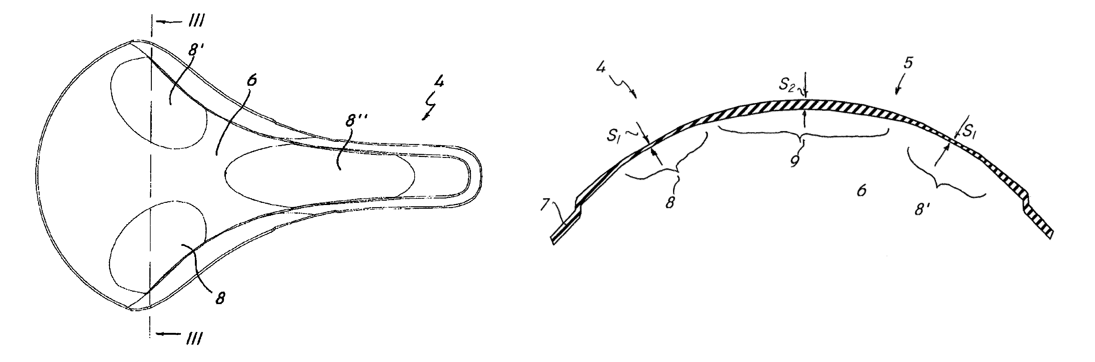
Figure 1 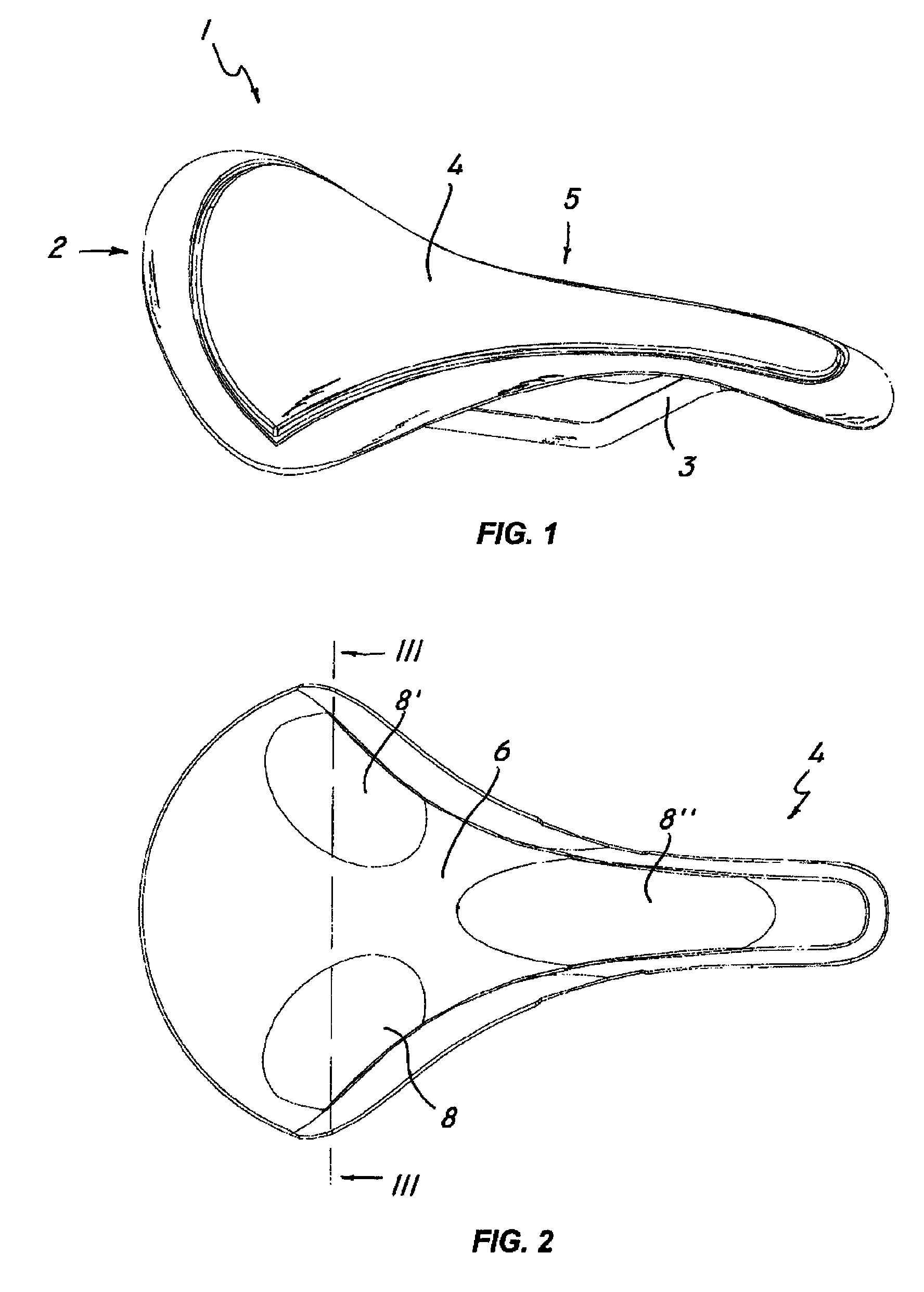
Figure 2 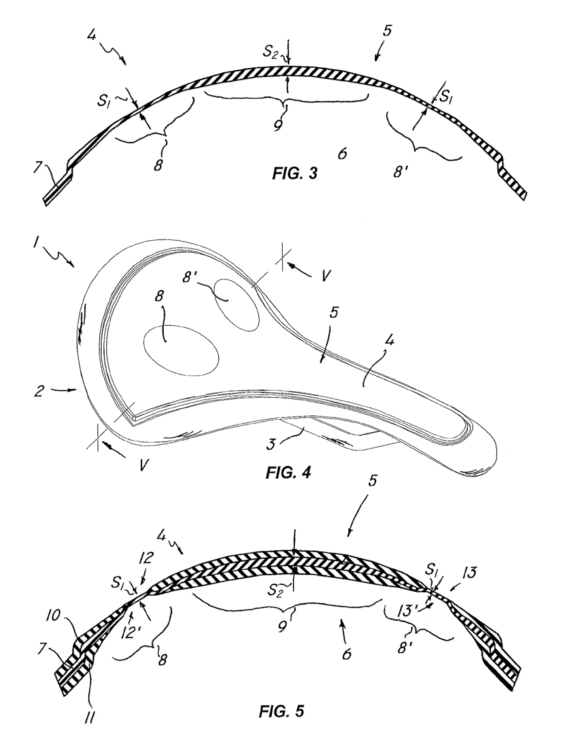
Figure 3
Abstract
Description
BACKGROUND
[0001] 1. Technical Field
[0002] The present invention finds application in the art of sport and leisure and particularly relates to a human body supporting structure and a method of making same.
[0003] Particularly, a human body supporting structure may be a bicycle saddle, a seating surface of a chair, a human body protection device, a shoe insole, a helmet, a glove and the like.
[0004] 2. Description of Related Art
[0005] Human body supports, particularly bicycle saddles, are known to include a shell for supporting a user's weight. Certain types of supports are further known to include a load-bearing shell having one or more differently deformable portions, i.e. having a higher resilience as compared with the rest of the shell.
[0006] These higher resilience portions, usually located in the areas of contact between the shell and certain sensitive areas of the user, may be formed using a variety of methods.
[0007] EP1305203, in the name of the same applicant, discloses a bicycle sadd...
Examples
first embodiment
[0040]FIG. 3 shows the invention, in which the shell 4 is made up of one sheet element 7 only. Nevertheless, it shall be understood that the shell 4 may also consist of multiple sheet elements of the same type, without departure from the inventive scope as defined in the annexed claims. This embodiment includes three differently deformable portions, with the first two portions, designated by numerals 8, 8′ being formed at the ischial area and the other, designated by numeral 8″, being formed at the prostatic area.
[0041]In this embodiment, the thickness S1 of the differently deformable area 8 is smaller than the thickness 52 of the other areas of the sheet element 7, e.g. the central area 9. Also, the average density ρ1 of the differently deformable portion 8 is greater than the average density ρ2 of the central area 9. The combination of these two characteristics will impart a higher deformability to the differently deformable portion 8 as compared to that of the central portion 9, ...
second embodiment
[0042]FIG. 5 shows the invention, in which the shell 4 is formed of a continuous sheet element 7 interposed between two discontinuous sheet elements 10, 11 having apertures 12, 12′ and 13, 13′ coincident with the differently deformable portions 8, 8′.
[0043]In this embodiment, the thickness S1 of the differently deformable area 8 is smaller than the thickness S2 of the other areas of the sheet element 7, e.g. the central area 9. Also, the average density ρ1 of the differently deformable portion 8 is greater than the average density ρ2 of the central area 9.
[0044]Advantageously, the discontinuous sheet elements 10, 11 may be formed of the same material as the continuous sheet element 7 and may have a different color from the latter, to create a pleasant color effect.
[0045]The ratio between the average thickness S1 of the continuous sheet element 7 at the differently deformable portion 8 and the average thickness S2 of the rest of the extension thereof may fall in a range from 0.1 to 0...