
Method for fabricating a cylindrical spring by compressive force
a cylindrical spring and compressive force technology, applied in the field of springs, can solve the problems of unsuitable bulgy structures, and achieve the effects of preventing localized buckling, high force, and long deflection
Patent Information
- Authority / Receiving Office
- US · United States
- Patent Type
- Patents(United States)
- Current Assignee / Owner
- Publication Date
- 2013-01-08
Smart Images
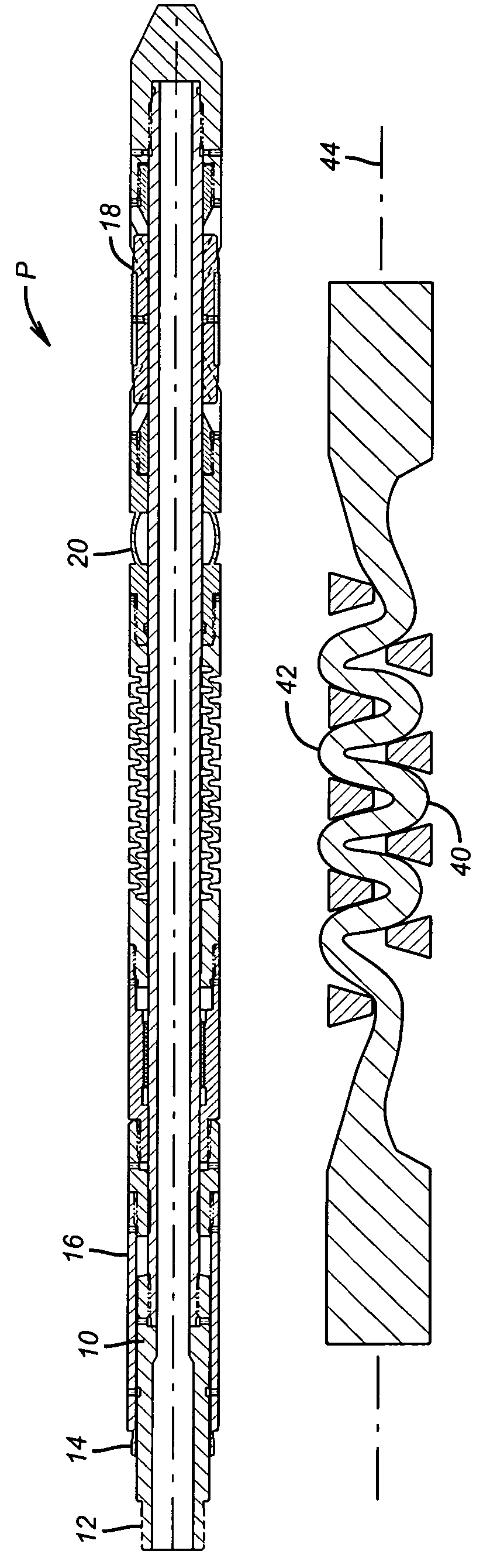
Figure 1 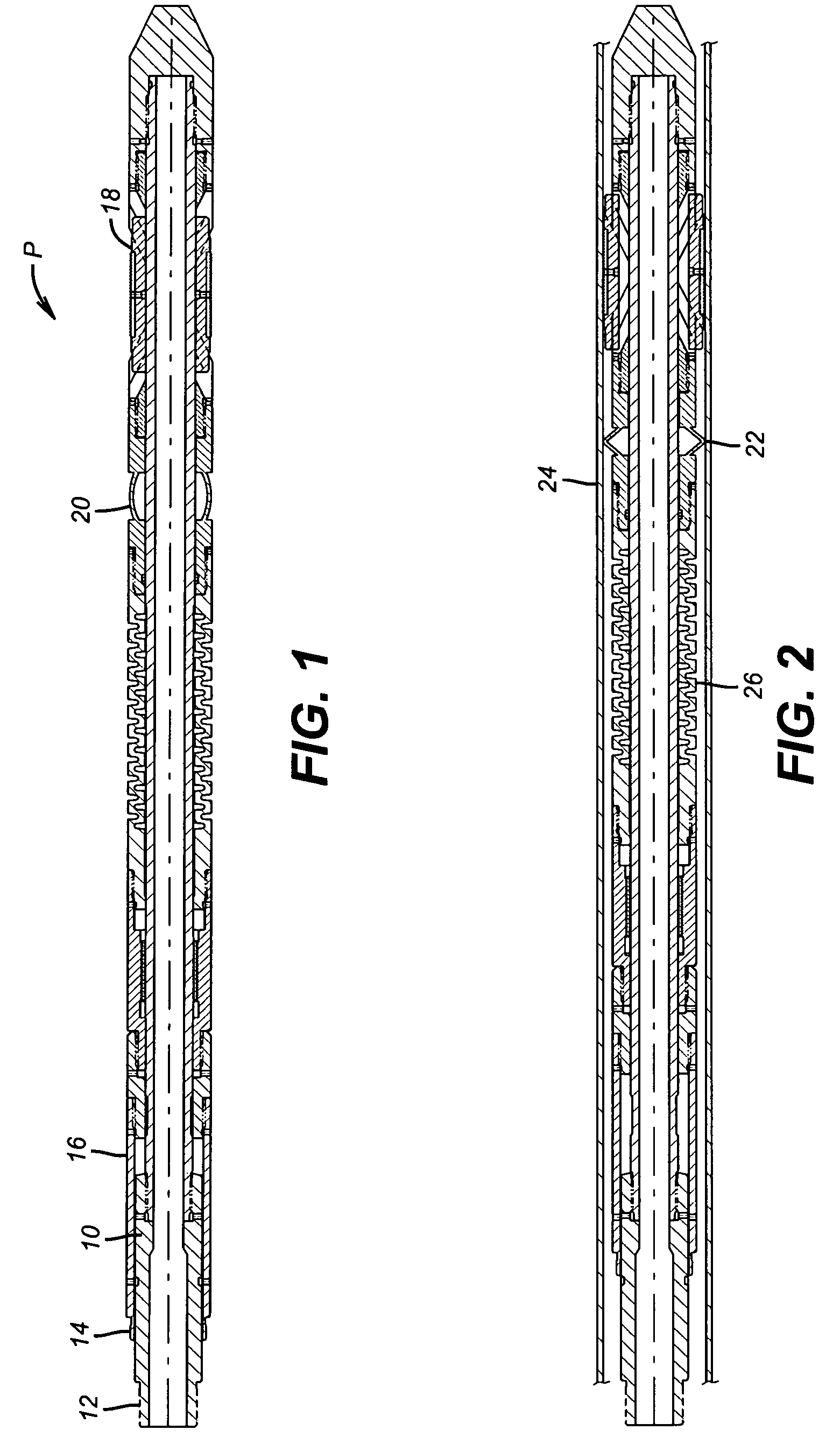
Figure 2 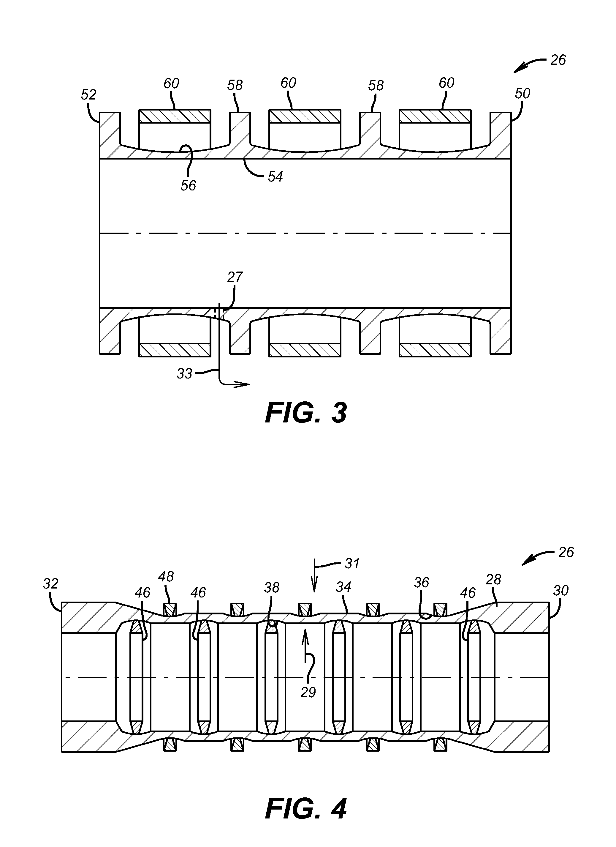
Figure 3
Abstract
Description
FIELD OF THE INVENTION
[0001] The field of this invention is springs and more particularly springs for downhole use where high force and a long deflection range is needed where the spring is a tubular structure created by compressive loading before or after assembly into a downhole tool.BACKGROUND OF THE INVENTION
[0002] Tubular shapes with wavy edges made from rubber or other plastics generally by molding the shape and compressing it when in service to serve as a spring are well known as shown in U.S. Pat. No. 5,141,697 (ribs control buckle locations); U.S. Pat. No. 4,235,427 (bellows wall on plastic tube); U.S. Pat. No. 5,326,083 (elastomer tubular shape for automotive use; U.S. Pat. No. 3,037,764 (elastomer tube with external scores used as a spring); U.S. Pat. No. 5,868,384 (steel tube surrounded by rubber cylinder with both compressed to make a spring with an internal stiffener); U.S. Pat. No. 3,409,284 (molded rubber cylindrical shape used a spring); U.S. Pat. No. 3,315,951 (bello...
Examples
Embodiment Construction
[0016]FIG. 1 illustrates an application of the present invention in a packer P. A mandrel 10 has attachment locations 12 and 14 for a setting tool that can shift sleeve 16 while retaining mandrel 10 to set the packer P. When the setting tool (not shown) is actuated the slips 18 are set first as shown in FIG. 2 followed by the collapsing and outward movement of the seal 20 as can also be best seen when comparing FIGS. 1 and 2. The seal 20 has a small dimension to allow clearance for run in and is shaped and scored so that it collapses about its center 22 to form a rounded edge that is driven radially into the surrounding tubular 24. While the structure of seal 20 is a known product now offered by Baker Hughes Incorporated, the device that retains the sealing force is now the tubular spring 26 of the present invention. As seen in these FIGS. it has a tubular shape with an undulating wall. In the preferred embodiment is it a metallic tube that is capable of delivering a force in excess...