
Parking lock system for an automatic transmission
a technology of automatic transmission and lock system, which is applied in the direction of brake systems, mechanical devices, transportation and packaging, etc., can solve the problems of high adjustment complexity during installation of parking lots, damage to transmission, and impaired driving safety,
Patent Information
- Authority / Receiving Office
- US · United States
- Current Assignee / Owner
- Publication Date
- 2013-06-11
Smart Images
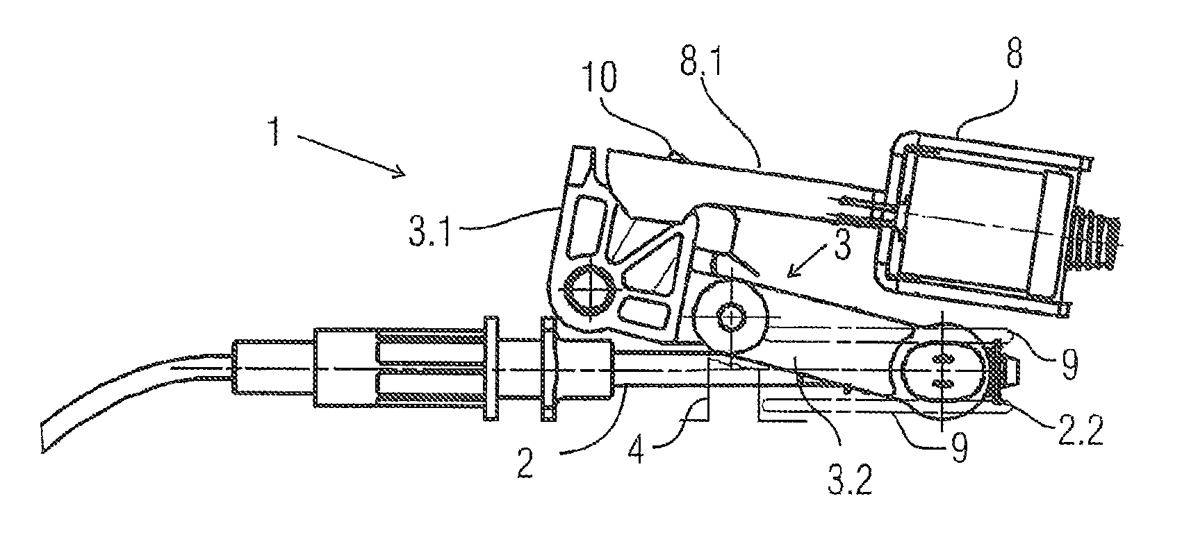
Figure 1 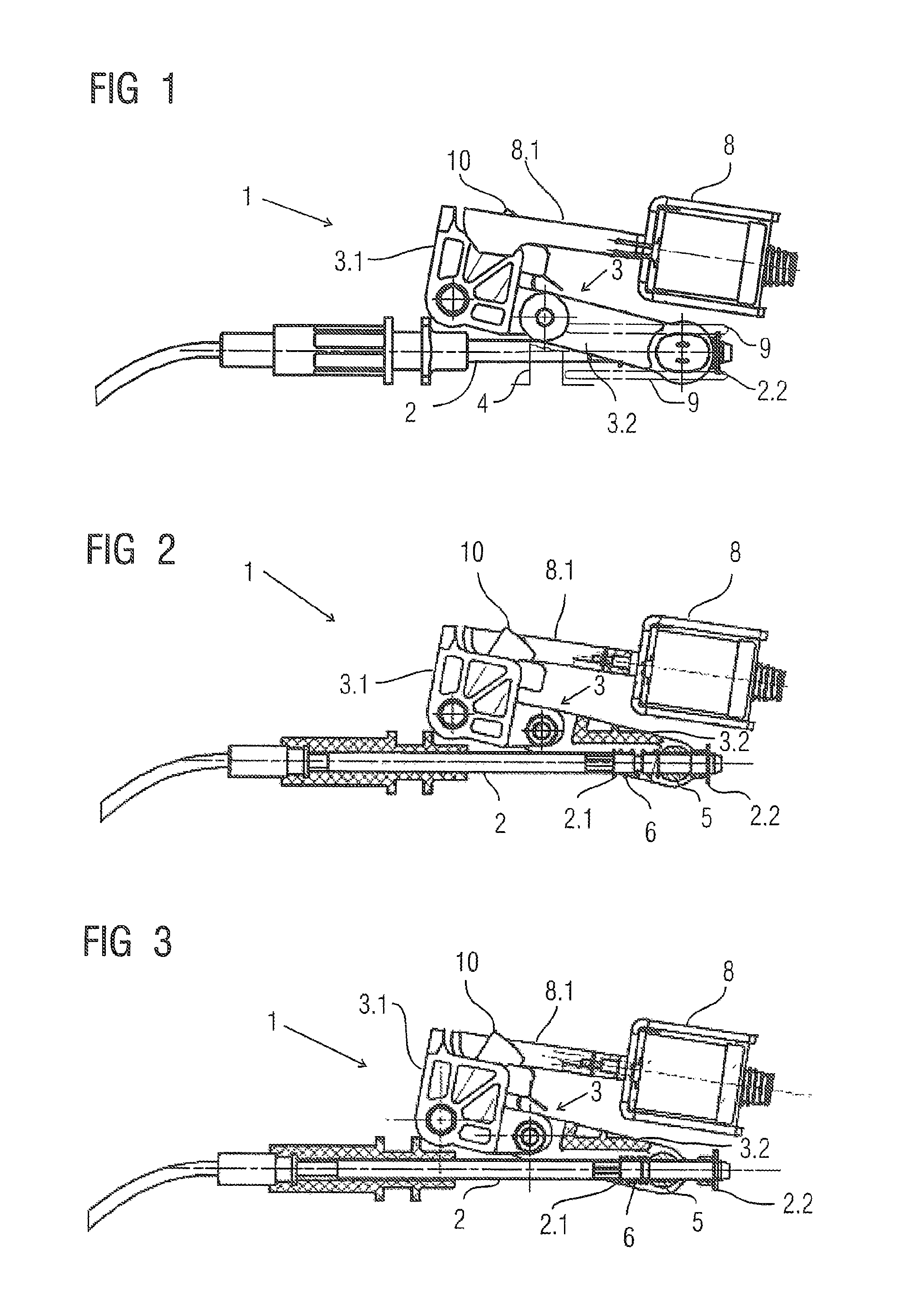
Figure 2 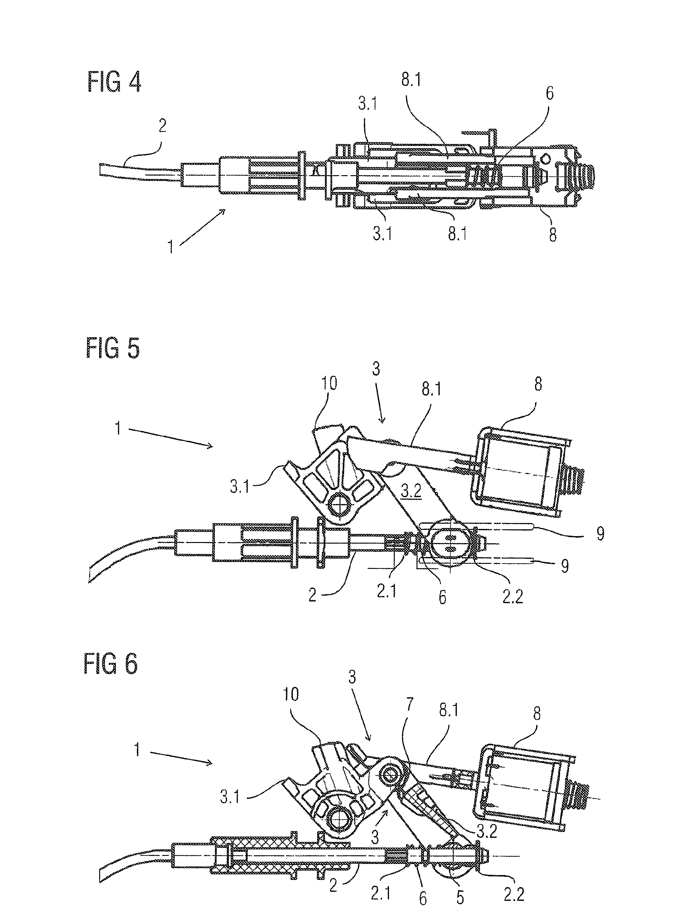
Figure 3
Abstract
Description
[0001] This is an application filed under 35 USC §371 of PCT / DE2009 / 050011, claiming priority to DE 10 2008 000 857.5 filed on Mar. 27, 2008.BACKGROUND OF THE INVENTION
[0002] (1) Field of the Invention
[0003] The invention relates to a parking lock system for an automatic transmission of a motor vehicle, wherein the automatic transmission has an actuator which can disengage a locking element in the automatic transmission, with the locking element being held in the locked position by spring force, and a locking assembly is provided which is connected to the locking element by means of an actuating element and which has a knee lever which can fix the actuating element so as to prevent engagement of the locking element in the automatic transmission.
[0004] (2) Description of Related Art
[0005] Parking lock systems of this type are required in conjunction with automatic transmissions of motor vehicles. They are used to prevent in the event of a system failure a locking element in the automatic ...
Examples
Embodiment Construction
[0032]FIG. 1 shows a locking assembly 1 according to the invention of a parking lock system of an automatic transmission for a motor vehicle in a side view. Shown is a Bowden cable 2, which is directly connected with the positioning of a locking element of the parking lock system on an automatic transmission of a motor vehicle and which moves synchronously with the positioning of this locking element in the longitudinal direction. A knee lever 3 consisting of a first attached lever arm 3.1 and a second free lever arm 3.2 is attached on the end of the Bowden cable 2, wherein the first attached lever arm 3.1 is rotatably affixed on one side of an attached axis, whereas the other side is connected via a freely movable axis with the second free lever arm 3.2. The second free lever arm 3.2 is rotatably attached on the end of the Bowden cable 2.
[0033]FIG. 2 shows the knee lever 3 shortly before the maximally extended position, wherein overextending causes the knee lever to move against a ...