
Heat exchanger for centrifugal compressor gas sealing
a centrifugal compressor and gas sealing technology, which is applied in the direction of machines/engines, liquid fuel engines, lighting and heating apparatus, etc., can solve the problems of gas treatment, harmful gas, and sudden perishing of washers, o-rings and vital parts of the gas seal, and achieve the effect of lowering the temperature of the seal
Patent Information
- Authority / Receiving Office
- US · United States
- Current Assignee / Owner
- Publication Date
- 2014-08-26
Smart Images
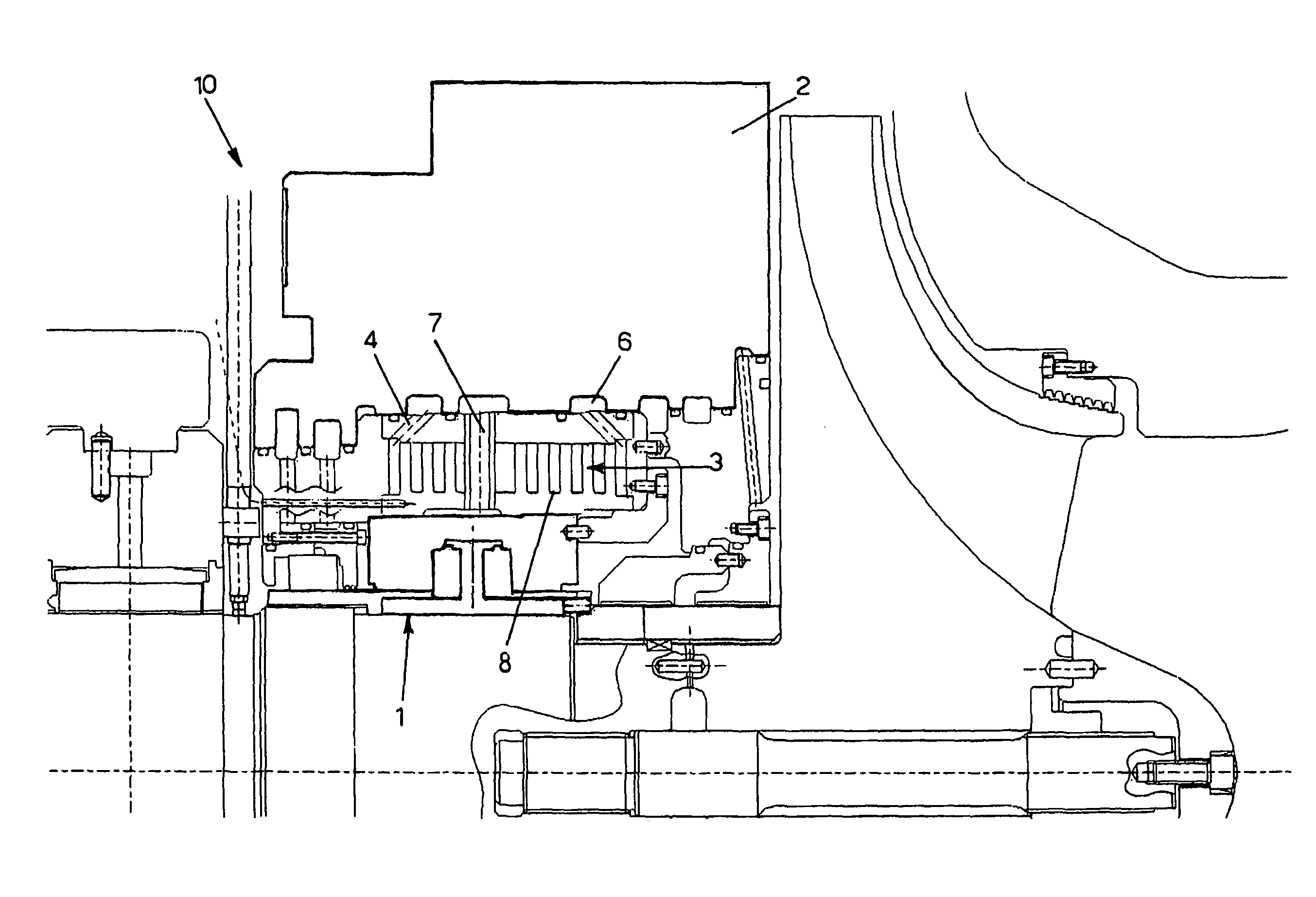
Figure 1 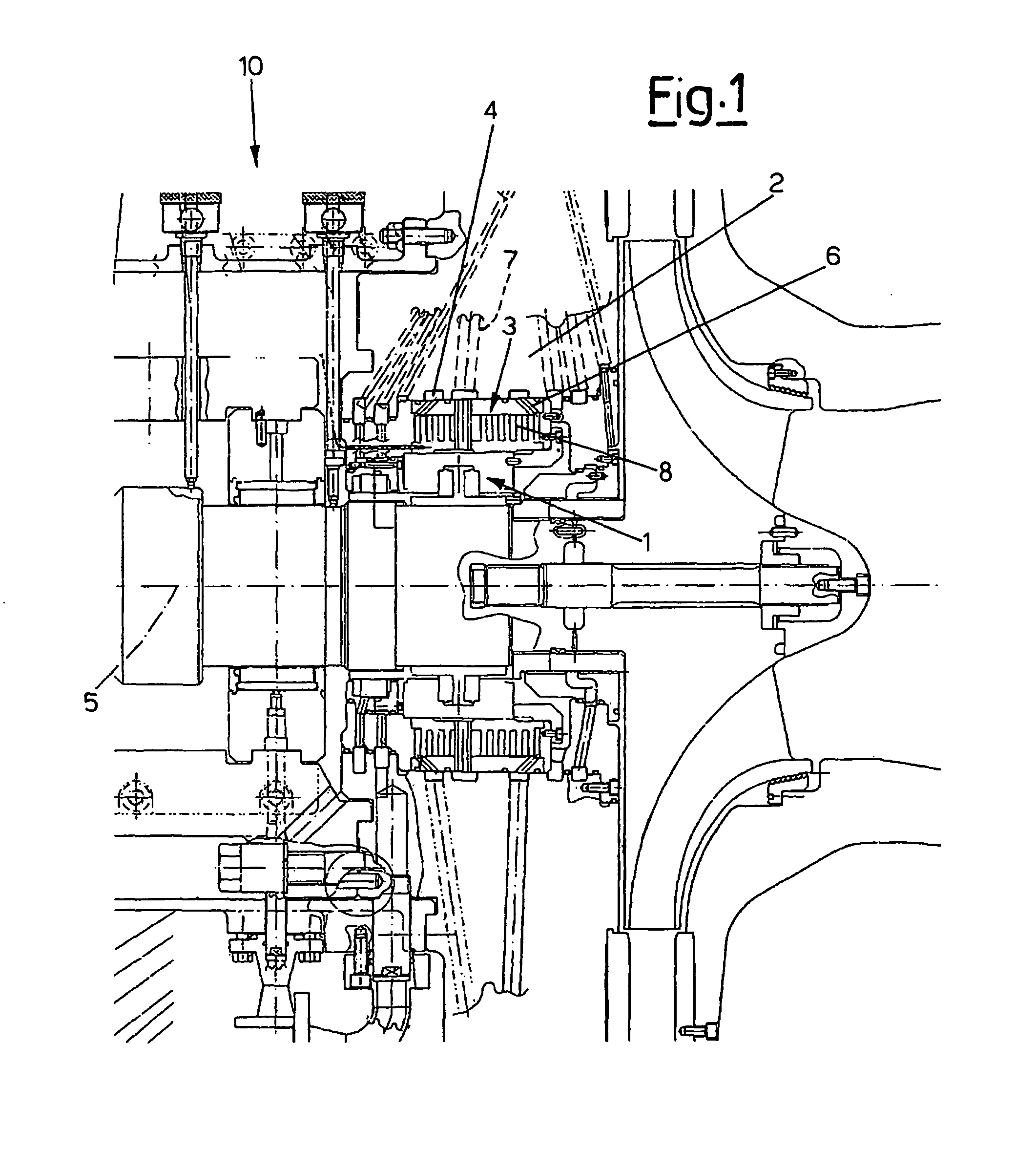
Figure 2 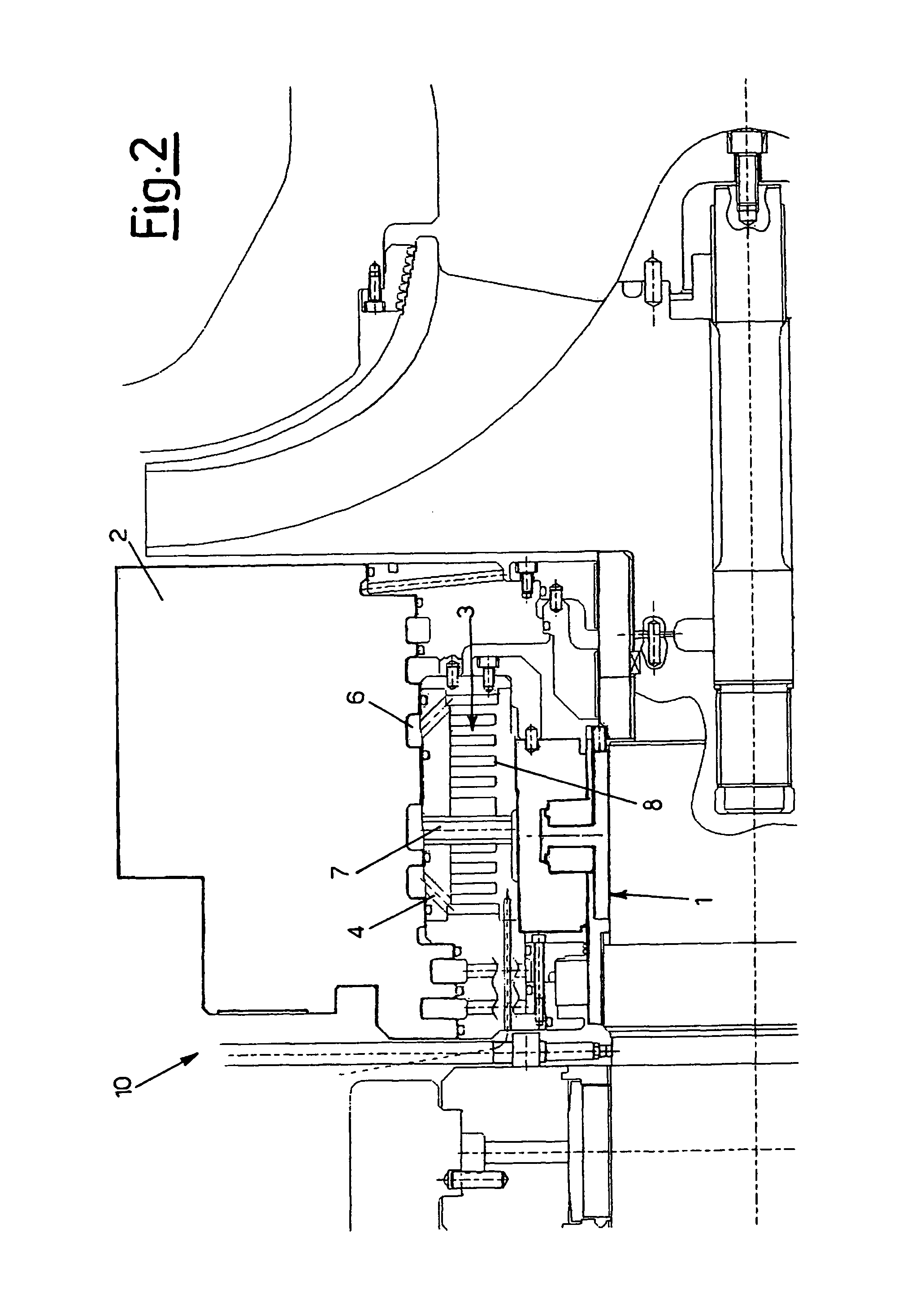
Figure 3
Abstract
Description
FIELD OF THE INVENTION
[0001] The present invention relates to a heat exchanger device for a gas seal for centrifugal compressors.DESCRIPTION OF BACKGROUND
[0002] As is known, a centrifugal compressor is a machine which returns a compressible fluid at a higher pressure than that at which it received it, giving it the necessary energy for the pressure change, by the use of a rotor with one or more impellers.
[0003] Each impeller, which is connected to the rotor, comprises a certain number of blades, radially arranged, which transfer energy to the gas. The centrifugal step also comprises stator parts which contribute to converting the kinetic energy of the impeller into gas pressure energy and cause the gas flow in the compressor.
[0004] The gas compression area is delimited by walls, generally flanges, which support gas seals suitable for preventing the pressurized gas from leaving the compressor.
[0005] After compression, the temperature of the gas at the compressor delivery can reach a high ...
Examples
Embodiment Construction
[0023]With reference to the figures, these show a gas seal 1 according to the present invention situated directly downstream of the impellers and supported by a flange 2 to prevent the process gas, i.e. the gas compressed by the compressor 10, being discharged into the environment. The seal 1 is equipped with a fluid heat exchanger 3, situated between the seal 1 and the housing wall of the seal 1. The exchanger 3 is a cylindrical circular exchanger, arranged in an axial direction with respect to the shaft 5 of the impeller(s) so as to enfold the seal 1, as shown in FIG. 1.
[0024]The exchanger 3 also extends between the seal 1 and the supporting flange 2 of the seal itself and is fixed to this with the known means.
[0025]Again with reference to FIGS. 1 and 3, the exchanger 3 comprises at least one inlet opening 4 and at least one outlet opening 6 of the cooling liquid, which are situated above.
[0026]The openings 4 and 6 are connected to each other by means of a coiled path 8 for the co...