
Pneumatic tire with tread having zigzag sipes and narrow grooves
a technology of zigzag sipes and pneumatic tires, which is applied in the direction of non-skid devices, transportation and packaging, vehicle components, etc., can solve the problems that the ice performance is not always achieved with the conventional narrow groves, and achieves poor drainage, improved drainage, and improved edge effect.
Patent Information
- Authority / Receiving Office
- US · United States
- Patent Type
- Patents(United States)
- Current Assignee / Owner
- Publication Date
- 2015-03-03
Smart Images
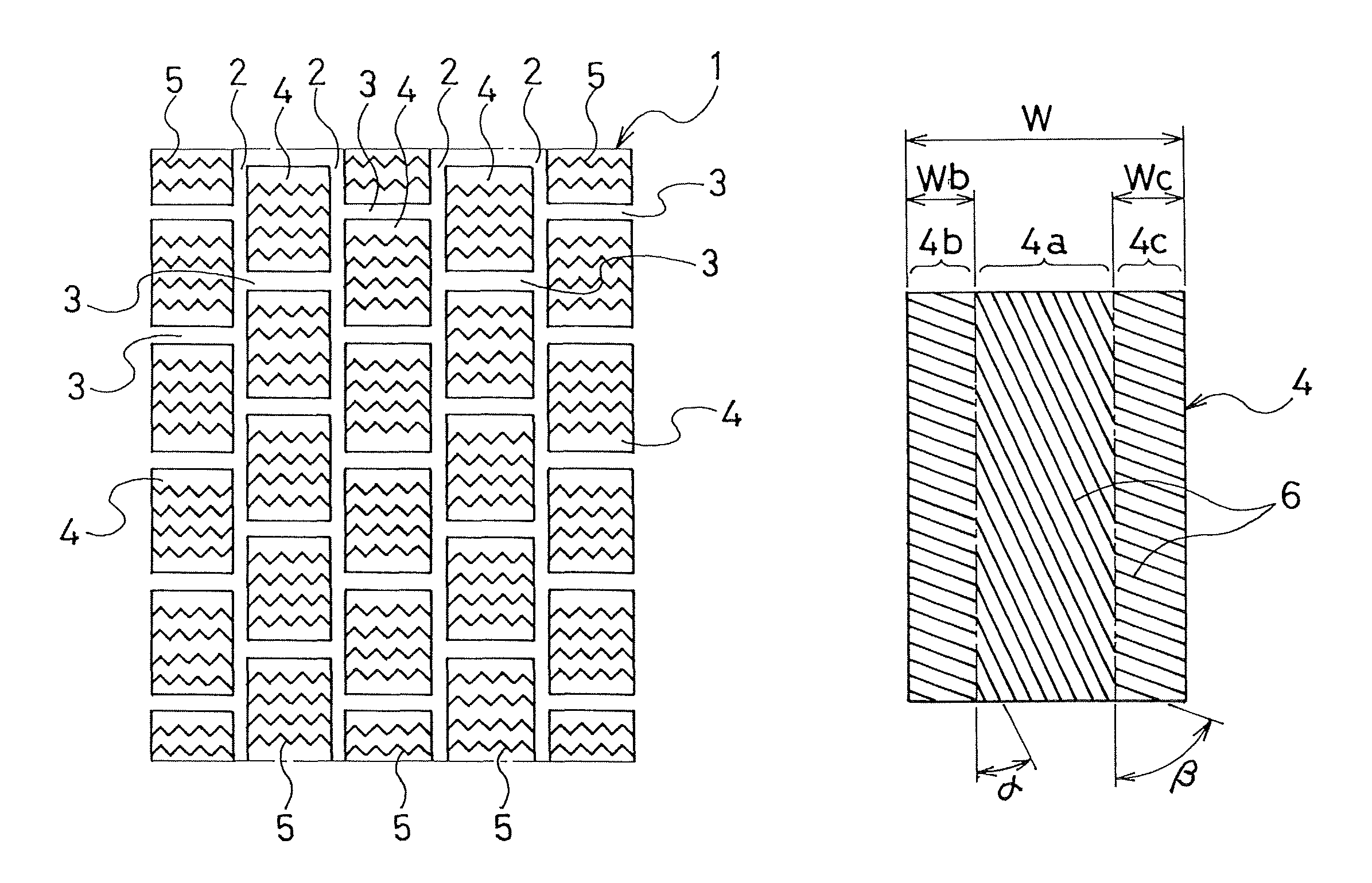
Figure 1 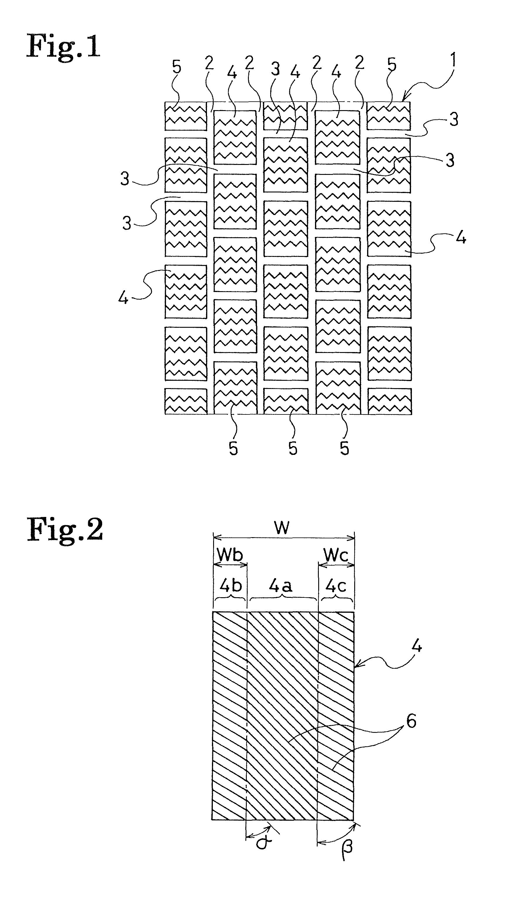
Figure 2 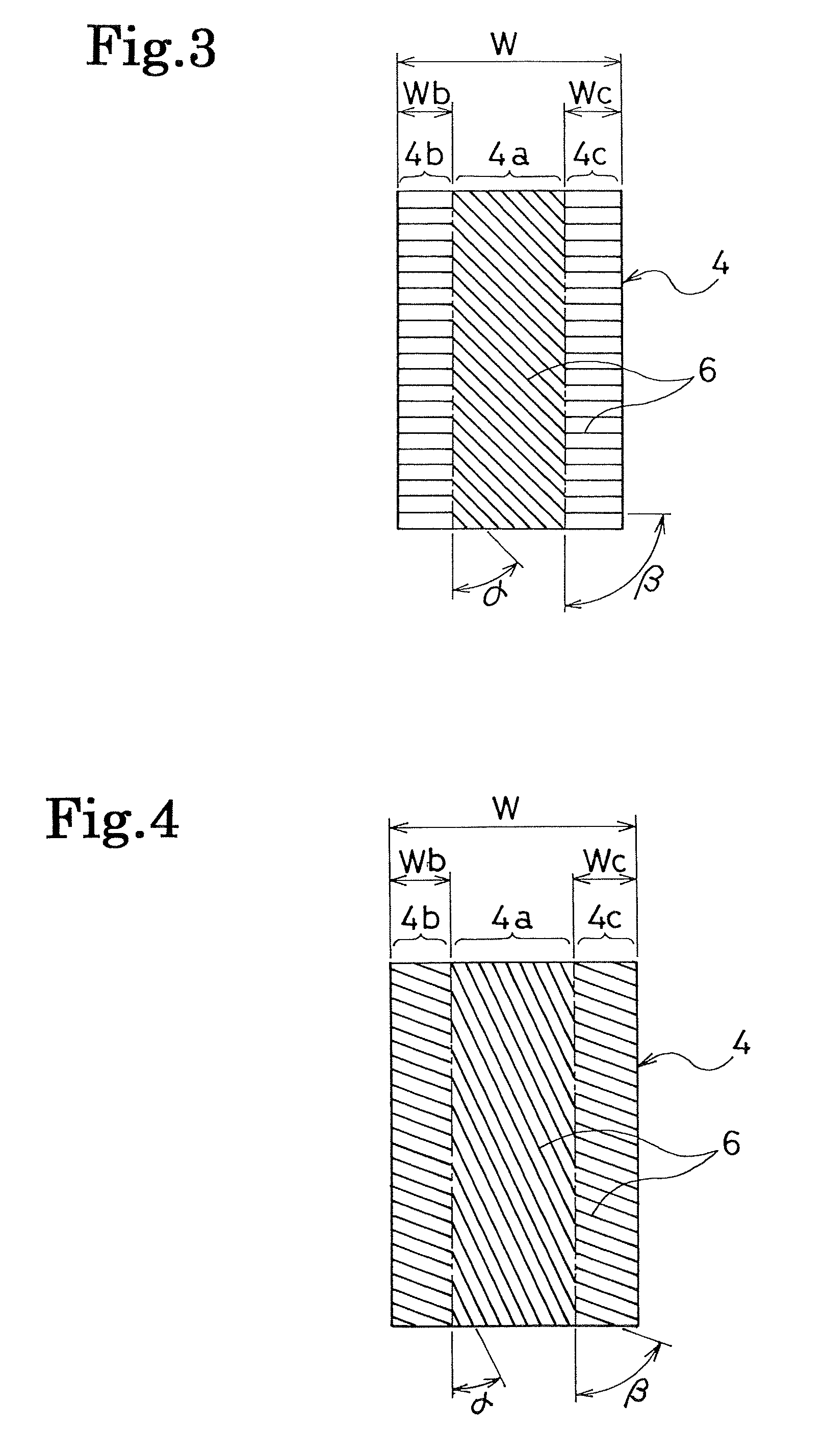
Figure 3
Abstract
Description
TECHNICAL FIELD
[0001] The present invention relates to a pneumatic tire provided with narrow grooves in a ground contact surface of each land section. More specifically, the present invention relates to a pneumatic tire having further improved ice performance achieved by narrow grooves.BACKGROUND ART
[0002] All-season tires and studless tires include, in their treads, multiple partitioned land sections each formed of a block or a rib, and multiple sipes are formed in each of the land sections. In order for such a pneumatic tire to achieve sufficient ice performance while the tire is brand-new and hence cannot obtain inherent properties of rubber, multiple narrow grooves each being shallower than a sipe are provided in a ground contact surface of each land section (see, for example, Patent Document 1).
[0003] The above-mentioned narrow grooves are generally arranged at certain pitches in a certain direction in the ground contact surface of each land section. When such narrow grooves are p...
Examples
examples
[0030]Tires of a conventional example 1 and examples 1 to 10 were manufactured. Each of the tires was a pneumatic tire for ice-bounded or snow-covered roads with a tire size of 195 / 65R15. The tire including, in a tread, multiple land sections (blocks) formed by partitioning the tread by grooves, was provided with multiple sipes in each land section and with multiple narrow grooves in the ground contact surface of each land section. The tires varied in angle α (°) of tilt of the narrow grooves relative to the tire's circumferential direction in the center region of each land section, the angle β (°) of tilt of the narrow grooves relative to the tire's circumferential direction in each end region of the land section, and ratio (%) in width of each end region to the land section, as shown in Table 1. In the conventional example 1 and the examples 1 to 10, the percentage in area of the narrow grooves in each land section was set at 35%, the depth of the narrow grooves was set at 0.3 mm,...