
Bushing
a technology of bushings and shock absorbers, applied in the field of bushings, can solve the problems of increasing the load of suspensions that need to be withstood, introducing packaging problems in the design of suspensions, and affecting the performance of suspensions, so as to reduce the load of high shocks, prevent the increase of stiffness, and control the stiffness of the bushings
Patent Information
- Authority / Receiving Office
- US · United States
- Patent Type
- Patents(United States)
- Current Assignee / Owner
- Publication Date
- 2015-03-03
- Estimated Expiration
- Not applicable · inactive patent
Smart Images
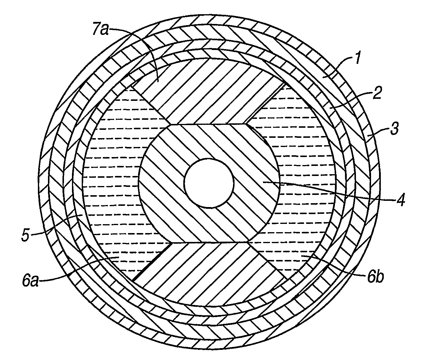
Figure 1 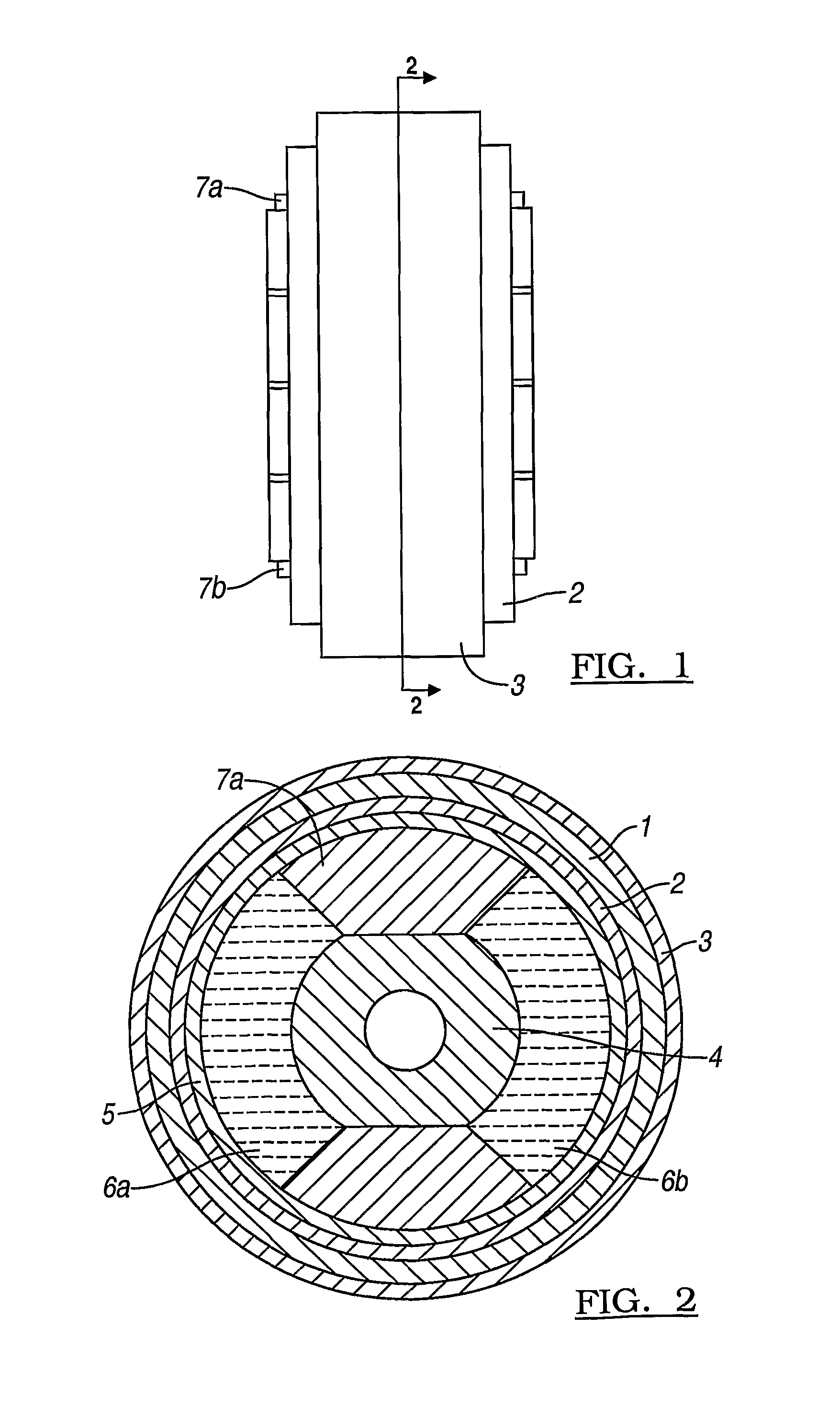
Figure 2 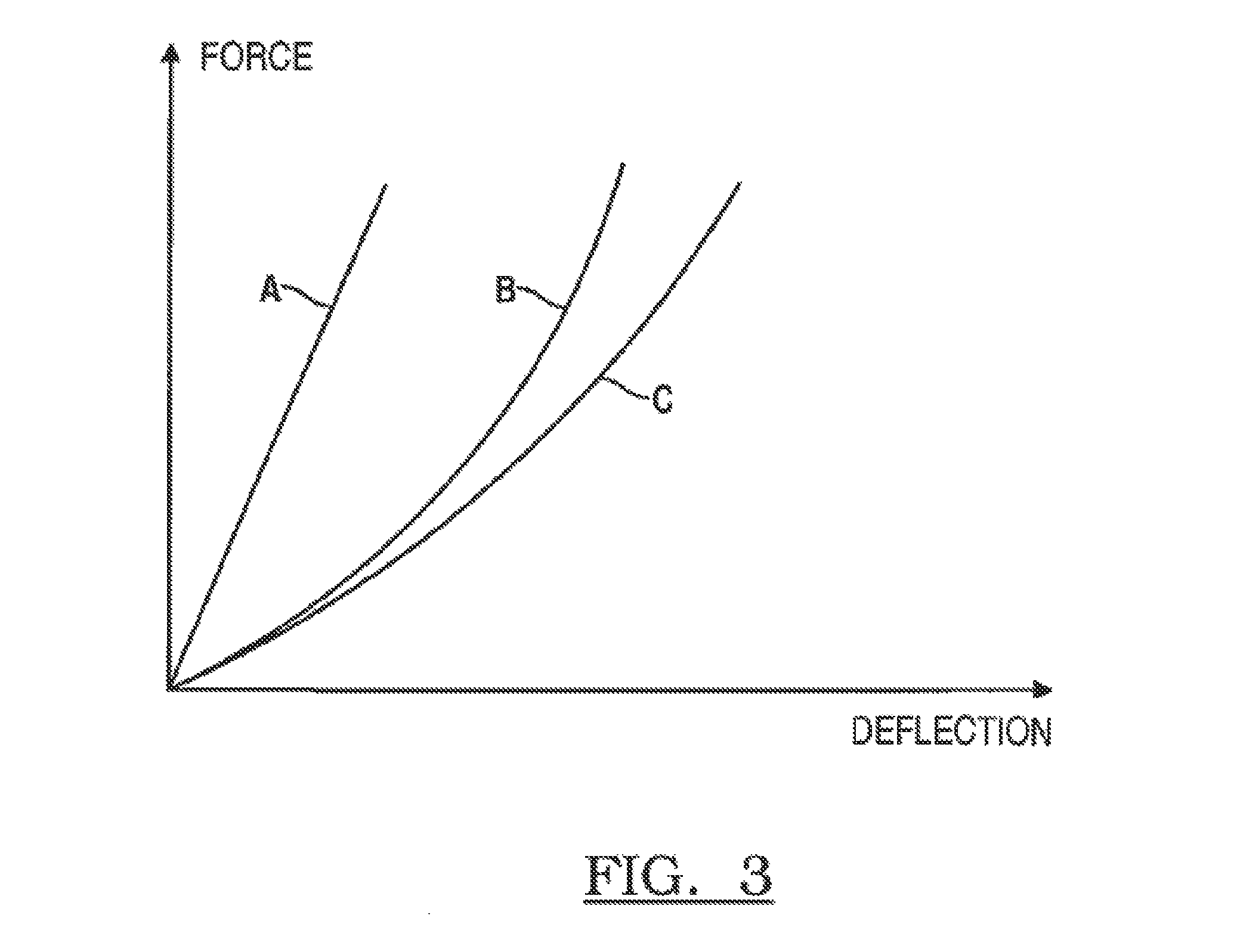
Figure 3
Abstract
Description
CROSS-REFERENCE TO RELATED APPLICATIONS
[0001] This application claims foreign priority benefits under 35 U.S.C. §119(a)-(d) to GB 0720476.1 filed Oct. 19, 2007, which is hereby incorporated by reference in its entirety.BACKGROUND OF THE INVENTION
[0002] 1. Field of the Invention
[0003] The present invention relates to bushings and particularly, though not exclusively, to bushings for use in motor vehicle suspension systems.
[0004] 2. Background Art
[0005] Typically, a bushing is located between a suspension component e.g. one end of a wishbone and the vehicle chassis or body. The bushing incorporates a resilient component for the purposes of cushioning shocks, reducing vibrations transmitted from the vehicle's wheels to the vehicle body and passengers and allowing movement of the vehicle relative to the vehicle body.
[0006] One known type of bushing consists of inner and outer metal cylindrical sleeves separated by a piece of rubber. It can be designed to have a linear or non-linear deflection...
Examples
Embodiment Construction
)
[0017]The bushing of FIGS. 1 and 2 comprises an inner hydraulic bushing in series with an outer rubber bushing.
[0018]The outer rubber bushing comprises a cylindrical piece of rubber 1 supported around its inner and outer perimeters by metal cylinders 2 and 3 respectively. This outer rubber bushing has a stiffness characteristic as illustrated by curve A in FIG. 3 i.e. its deflection increases in a substantially linear fashion with increasing applied force.
[0019]The inner hydraulic bushing is supported by a central metal portion 4 and the inner metal cylinder 2. This hydraulic bushing comprises an annular outer piece of rubber 5 which encloses two hydraulic fluid-filled chambers 6a, 6b, separated by two rubber portions 7a, 7b. This inner hydraulic bushing has a stiffness characteristic as illustrated by curve B in FIG. 3 i.e. it has a progressive stiffness whereby for comparatively low applied forces its deflection increases in a substantial fashion whereas for increasingly high app...