
Downhole tools and methods for selectively accessing a tubular annulus of a wellbore
a wellbore and tubular annulus technology, applied in the direction of wellbore/well accessories, fluid removal, construction, etc., can solve the problems of high cost and risk of multiple trips, bridge plugs can become stuck in the wellbore and need to be drilled out at great expense, block or otherwise damage some successfully fractured zones, etc., to improve the quality of stimulation, minimizing fluid/proppant, and minimizing flow restrictions
Patent Information
- Authority / Receiving Office
- US · United States
- Patent Type
- Patents(United States)
- Current Assignee / Owner
- Publication Date
- 2017-02-07
Smart Images
Figure 1 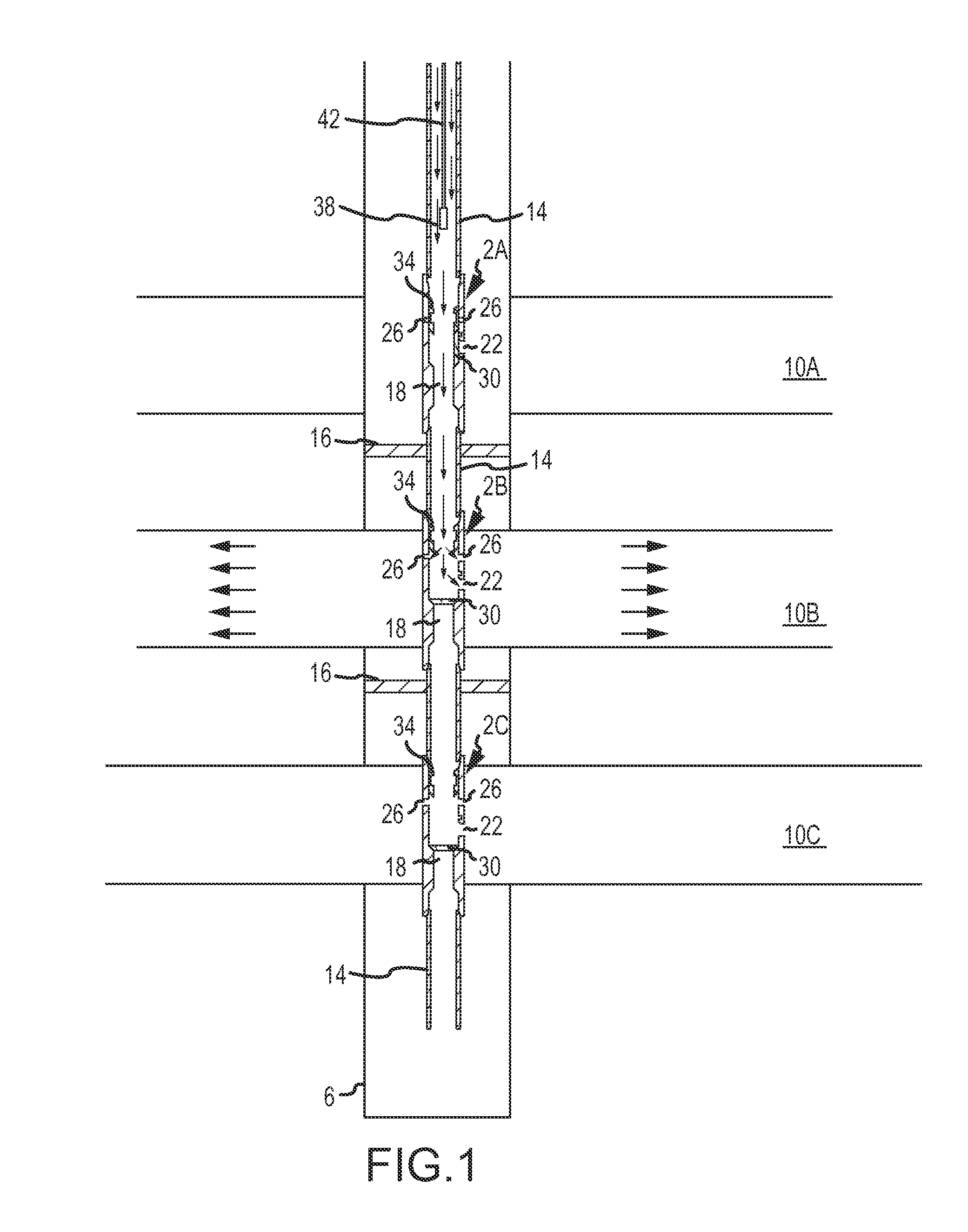
Figure 2 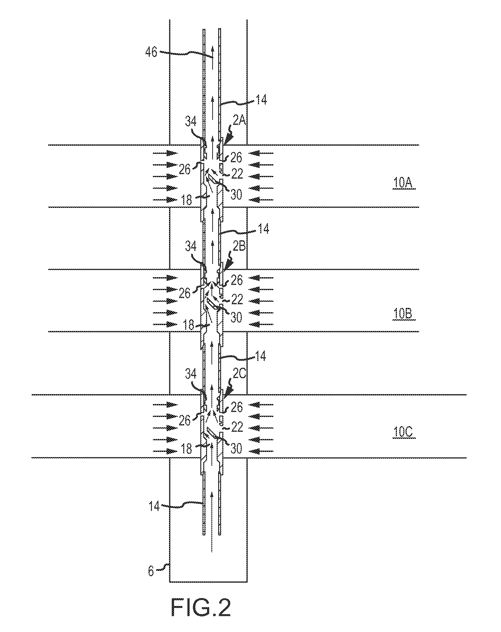
Figure 3
Abstract
Description
CROSS REFERENCE TO RELATED APPLICATION
[0001] This application is a continuation-in-part of U.S. patent application Ser. No. 13 / 267,691, filed Oct. 6, 2011, which claims the benefit of U.S. Provisional Application No. 61 / 390,354, filed Oct. 6, 2010, the entire disclosures of which are hereby incorporated herein by reference in their entirety.FIELD OF THE INVENTION
[0002] Embodiments of the present invention are generally related to selectively opening and closing one or more ports or access openings in a tubular string. More specifically, one embodiment allows selective access of a tubular annulus of a wellbore to provide a flow path between a tubular string positioned in the wellbore and a geologic formation that requires a treatment such as hydraulic fracturing.BACKGROUND OF THE INVENTION
[0003] A wellbore used in recovering oil / gas typically includes a production string placed within a casing string. In some wellbore designs, the entire length of the wellbore is lined with the casing s...
Examples
Embodiment Construction
[0084]FIGS. 1 and 2 show one embodiment of the present invention in which at least one downhole tool 2 and associated tubular string 14 is disposed in a wellbore 6. According to this embodiment, the wellbore 6 is drilled through a subterranean formation. As shown in FIGS. 1 and 2, three tools 2 are connected to a tubular string 14. Each tool 2 is vertically disposed within a formation 10A, 10B, 10C that has been selected to be fracture stimulated and / or produced. One of skill in the art will appreciate that packers, cement, or other sealants may be located on either side of the formation 10A, 10B, and 10C to provide annular hydraulic isolation. As shown in FIG. 1, packers 16 provide annular hydraulic isolation of formation 10B. In this embodiment, each tool 2 has an axial bore 18, a lateral bore 22, fracture ports 26, a flapper valve 30, and a sliding sleeve 34.
[0085]Referring now to FIG. 1, a fracture stimulation of a multiple zone formation is shown. As illustrated, the lower form...