
DC-DC converter input voltage high-energy transient clamping topology
a converter and input voltage technology, applied in the direction of electric variable regulation, process and machine control, instruments, etc., can solve the problems of high energy consumption of input voltage transients, damage to electrical components and systems, and damage to many times, so as to achieve high reliability, low cost, and tight performance specifications
Patent Information
- Authority / Receiving Office
- US · United States
- Patent Type
- Patents(United States)
- Current Assignee / Owner
- Publication Date
- 2018-05-22
Smart Images
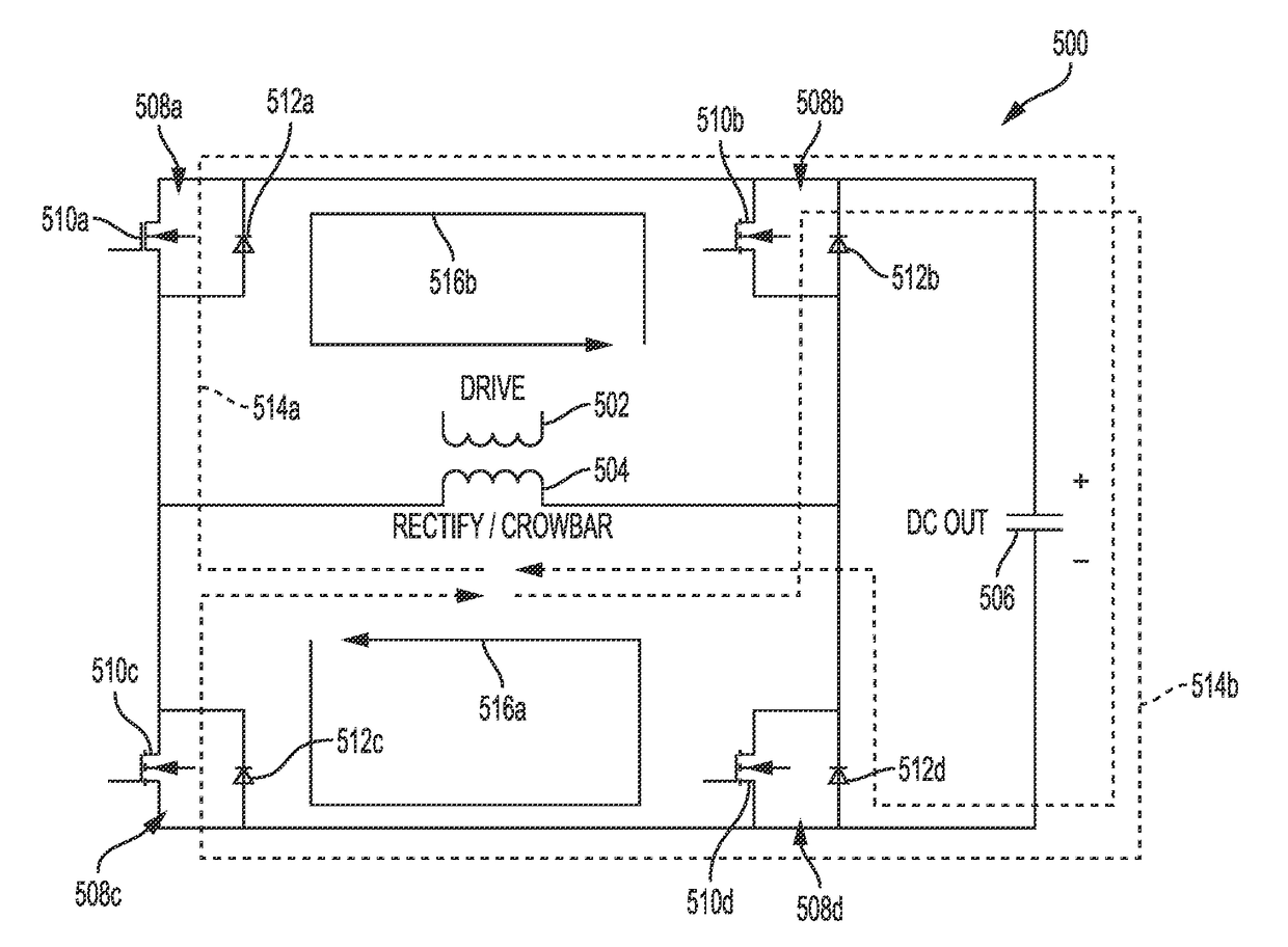
Figure 1 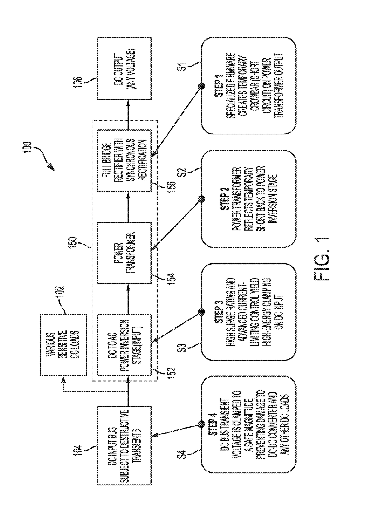
Figure 2 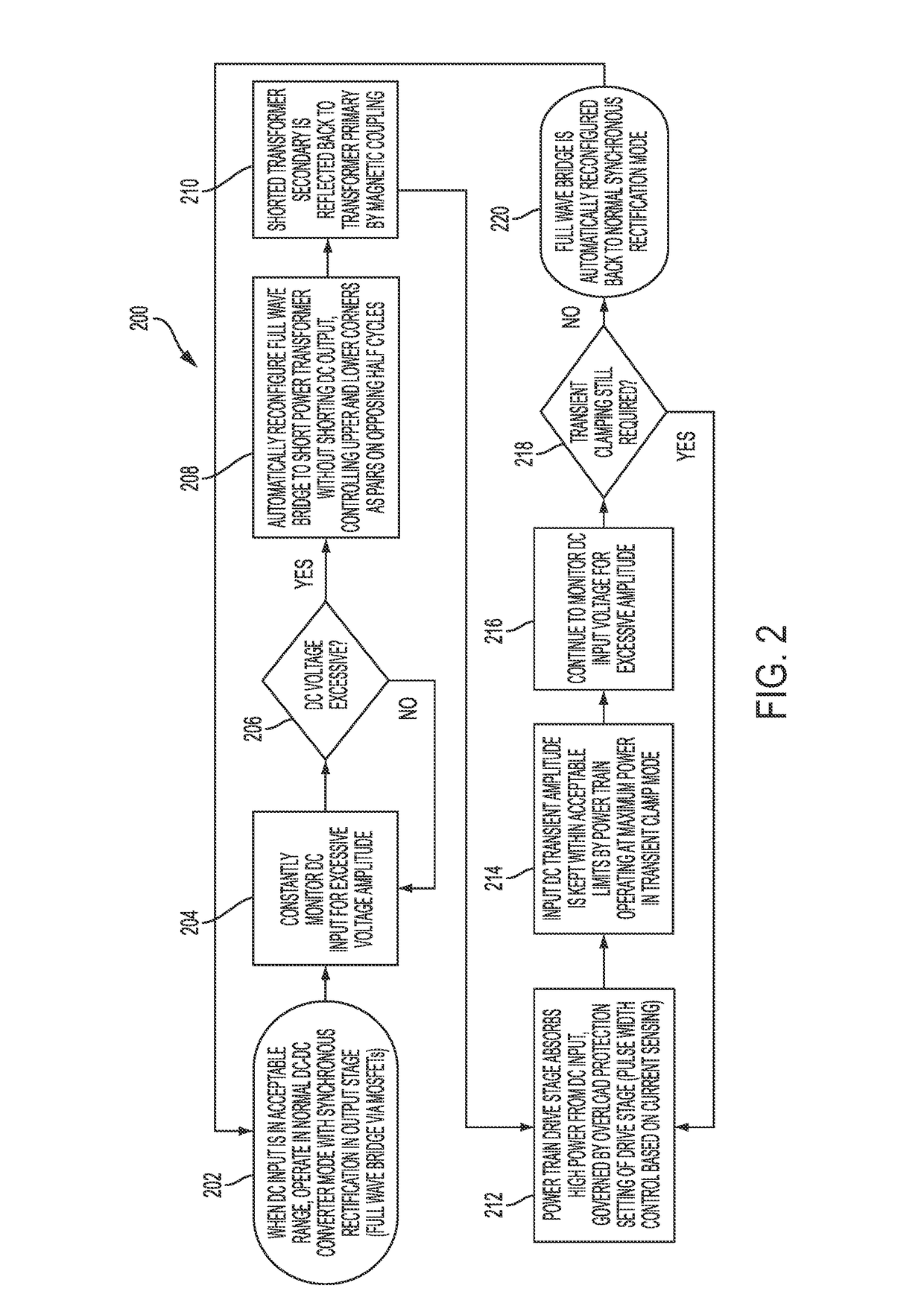
Figure 3
Abstract
Description
BACKGROUND OF THE INVENTION1. Field of the Invention
[0001] The subject disclosure relates to methods and systems for clamping high-energy transients in applications such as battery-based systems.2. Background of the Related Art
[0002] As is well-known, electrical components and systems can be subject to damage when subjected to excessive voltage and / or current transients. Even though components and circuits typically have some design margin and various efforts have been made at dealing with transients, damage still often occurs. One area with particular problems in dealing with transients is automotive applications and, in particular, electric vehicles. Evolving battery-based system applications of DC-DC converters and other DC loads can include destructive input voltage transients having very high energy. The traditional transient clamping techniques of metal oxide varistor (MOV), diode-based transient suppressors, and spark gaps provide protection that is limited.
[0003] One example of...
Examples
Embodiment Construction
[0014]The subject technology overcomes many of the prior art problems associated with transients in electrical systems. The advantages, and other features of the systems and methods disclosed herein, will become more readily apparent to those having ordinary skill in the art from the following detailed description of certain preferred embodiments taken in conjunction with the drawings which set forth representative embodiments of the present invention and wherein like reference numerals identify similar structural elements. It is understood that references to the figures such as up, down, upward, downward, left, and right are with respect to the figures and not meant in a limiting sense.
[0015]Referring now to FIG. 1, a block diagram representation of a clamping topology 100 in accordance with the subject disclosure is shown. The topology 100 protects various sensitive DC loads 102 being powered by a DC input bus 104, which may be subject to destructive transients. The topology 100 p...