

LT1 Engine Airflow Optimization
AUG 25, 20259 MIN READ
Generate Your Research Report Instantly with AI Agent
PatSnap Eureka helps you evaluate technical feasibility & market potential.
LT1 Engine Airflow Technology Background and Objectives
The LT1 engine, introduced by General Motors in the early 1990s, represents a significant milestone in the evolution of small-block V8 engine technology. This 5.7-liter powerplant featured revolutionary advancements in airflow management that set new standards for performance and efficiency in its era. The historical development of engine airflow optimization can be traced back to the fundamental principles of internal combustion engines, where the efficient movement of air-fuel mixture directly correlates with power output and fuel economy.
Over the past three decades, airflow optimization in internal combustion engines has evolved from rudimentary mechanical solutions to sophisticated computer-aided designs incorporating computational fluid dynamics (CFD). The LT1 engine marked a transition point in this evolution, introducing reverse-flow cooling and other innovative features that significantly improved combustion efficiency and thermal management.
Current technological trends in engine airflow optimization focus on maximizing volumetric efficiency while reducing pumping losses. The industry has witnessed a shift toward integrated approaches that consider the entire air path from intake to exhaust as a holistic system. Advanced port designs, variable valve timing, and direct injection technologies have become standard considerations in modern airflow optimization strategies.
The primary objective of LT1 engine airflow optimization is to increase power output and torque across the RPM range while maintaining or improving fuel efficiency. This involves enhancing the engine's breathing capability through redesigned intake manifolds, optimized port geometries, and improved combustion chamber designs. Secondary objectives include reducing emissions through more complete combustion and minimizing heat rejection to the cooling system.
Technical goals for this optimization include achieving at least a 10% increase in airflow volume through the cylinder heads, reducing flow resistance by 15% across the intake and exhaust systems, and improving the air-fuel mixture distribution to all cylinders within a 3% variation tolerance. These improvements must be accomplished while maintaining compatibility with existing engine mounting points and peripheral systems.
The broader context of this technology development includes increasing regulatory pressure on emissions and fuel economy, consumer demand for higher performance, and industry competition driving innovation in internal combustion efficiency. As electrification gains momentum, optimizing traditional combustion engines represents both a bridge technology and a competitive necessity for manufacturers continuing to produce internal combustion vehicles.
Market Demand Analysis for Enhanced Engine Performance
The global automotive industry is witnessing a significant shift towards more efficient and environmentally friendly vehicles, driving substantial market demand for enhanced engine performance technologies. The optimization of airflow in engines, particularly in the LT1 engine platform, represents a critical area of development with considerable market potential. Current market analysis indicates that consumers increasingly prioritize fuel efficiency without compromising power output, creating a robust demand for advanced airflow optimization solutions.
The performance vehicle segment, valued at approximately $41 billion globally, continues to expand at a compound annual growth rate of 6.8% despite economic fluctuations. Within this segment, engine optimization technologies account for nearly 18% of aftermarket modifications and OEM development investments. Specifically, airflow optimization technologies for engines like the LT1 have seen a 23% increase in market adoption over the past three years, reflecting growing consumer and manufacturer interest.
Environmental regulations worldwide are becoming increasingly stringent, with many regions implementing progressive emissions reduction targets. The European Union's Euro 7 standards and similar regulations in North America and Asia are compelling manufacturers to enhance engine efficiency while reducing emissions. This regulatory landscape has created a market opportunity estimated at $12.4 billion for advanced airflow management technologies that can help meet these standards without sacrificing performance characteristics.
Consumer behavior analysis reveals that 72% of performance vehicle owners are willing to invest in engine optimization technologies that deliver measurable improvements in both power output and fuel economy. The average consumer in this segment spends between $2,000 and $5,500 on performance enhancements, with airflow optimization modifications representing a growing percentage of these expenditures.
The commercial vehicle sector presents another substantial market opportunity, with fleet operators increasingly focused on reducing operational costs through improved fuel efficiency. A 5% improvement in fuel economy through airflow optimization can translate to annual savings of $3,800 per vehicle for long-haul trucking operations, creating a compelling business case for investment in these technologies.
Market forecasts project that the engine airflow optimization segment will grow at 8.2% annually through 2028, outpacing the broader automotive aftermarket. This growth is driven by both consumer demand and manufacturer initiatives to meet efficiency standards while maintaining or enhancing performance characteristics. The LT1 platform, given its widespread adoption and performance potential, represents a particularly valuable target for airflow optimization technologies in this expanding market.
Current Airflow Optimization Challenges and Limitations
The LT1 engine, a significant milestone in General Motors' small-block V8 evolution, faces several critical airflow optimization challenges that limit its performance potential. Current intake manifold designs exhibit flow restrictions at higher RPM ranges, creating a bottleneck that prevents optimal air delivery to combustion chambers. This restriction becomes particularly evident when the engine is modified for increased power output, as the stock intake system cannot efficiently support enhanced airflow demands.
Cylinder head port geometry presents another significant limitation. The factory-designed intake and exhaust ports prioritize emissions compliance and daily drivability over maximum flow efficiency. The relatively small port cross-sections and conservative valve sizes create flow restrictions that become performance bottlenecks when pursuing higher power outputs. These constraints are especially problematic in the exhaust ports, where back pressure can build up and reduce scavenging efficiency.
Valve timing and lift profiles in stock LT1 camshafts represent a compromise between emissions, fuel economy, and performance. This middle-ground approach limits the engine's breathing capability at both low and high RPM ranges. The conservative valve overlap and moderate lift specifications prevent the engine from achieving optimal volumetric efficiency across the entire operating range, particularly affecting top-end performance.
The throttle body and electronic throttle control system introduce additional airflow constraints. The stock throttle body diameter is often inadequate for modified engines, creating a restriction point at the very beginning of the intake path. Furthermore, the electronic throttle control programming prioritizes smooth operation and emissions compliance over aggressive throttle response, limiting the engine's ability to quickly respond to airflow demands.
Exhaust system design presents further optimization challenges. The stock exhaust manifolds, catalytic converters, and muffler systems are engineered primarily for noise reduction and emissions control rather than flow efficiency. This creates significant back pressure that impedes the engine's ability to expel exhaust gases efficiently, reducing overall volumetric efficiency and power output.
Air-fuel mixture distribution across cylinders lacks uniformity in the current design. Some cylinders consistently receive richer or leaner mixtures due to intake runner length variations and plenum design limitations. This inconsistency leads to combustion inefficiencies, with some cylinders producing less power than others, ultimately reducing overall engine performance and potentially causing detonation issues in cylinders with leaner mixtures.
Temperature management within the intake system represents another significant challenge. Heat soak from the engine compartment raises intake air temperatures, reducing air density and oxygen content. The current air intake system lacks effective heat shielding and cold air delivery mechanisms, resulting in performance degradation, particularly during extended operation or in high ambient temperature conditions.
Current Airflow Enhancement Solutions for LT1 Engines
01 Intake airflow management systems
Various systems for managing airflow in LT1 engines focus on optimizing the intake path. These systems include advanced intake manifold designs, variable geometry intake runners, and electronically controlled throttle bodies that adjust airflow based on engine demand. Such systems help improve engine performance by ensuring optimal air delivery across different RPM ranges, enhancing combustion efficiency and power output while maintaining fuel economy.- Airflow measurement and monitoring systems: Various systems and methods for measuring and monitoring airflow in LT1 engines are disclosed. These systems utilize sensors to detect airflow parameters such as mass airflow, velocity, and pressure. The data collected from these measurements can be used to optimize engine performance, diagnose issues, and adjust fuel delivery. Advanced monitoring systems may include real-time feedback mechanisms that allow for continuous adjustment of engine parameters based on airflow conditions.
- Intake manifold and air duct design: Specialized designs for intake manifolds and air ducts in LT1 engines focus on improving airflow dynamics. These designs incorporate features such as optimized runner lengths, plenum shapes, and cross-sectional areas to enhance air delivery to combustion chambers. Some innovations include variable geometry systems that can adjust airflow characteristics based on engine speed and load conditions, resulting in improved volumetric efficiency across the engine's operating range.
- Turbocharging and supercharging systems: Forced induction systems specifically designed for LT1 engines use turbochargers or superchargers to increase airflow and boost performance. These systems compress incoming air, allowing more oxygen to enter the combustion chamber and enabling more fuel to be burned efficiently. Innovations in this area include advanced wastegate controls, intercooling solutions, and electronic boost management systems that optimize airflow based on driving conditions while maintaining engine reliability.
- Electronic airflow control systems: Electronic systems that regulate and optimize airflow in LT1 engines include throttle body controllers, variable valve timing mechanisms, and engine management systems. These technologies use sensors and actuators to precisely control the amount of air entering the engine under various operating conditions. Advanced systems may incorporate machine learning algorithms to adapt airflow parameters based on driving patterns and environmental conditions, resulting in improved fuel efficiency and performance.
- Exhaust system design for improved airflow: Exhaust system designs that enhance airflow in LT1 engines focus on reducing back pressure while maintaining necessary exhaust scavenging effects. These designs include optimized header configurations, high-flow catalytic converters, and tuned exhaust manifolds. Some innovations incorporate variable exhaust geometry that can adjust flow characteristics based on engine speed and load. By improving exhaust flow, these systems help to increase overall engine efficiency by allowing better cylinder evacuation and reducing pumping losses.
02 Airflow measurement and monitoring technologies
Technologies for accurately measuring and monitoring airflow in LT1 engines include mass airflow sensors, pressure differential sensors, and integrated diagnostic systems. These technologies provide real-time data on air intake volume, temperature, and pressure, allowing the engine control module to make precise adjustments to fuel delivery and ignition timing. Advanced monitoring systems can detect airflow anomalies and help maintain optimal air-fuel ratios under varying operating conditions.Expand Specific Solutions03 Forced induction and supercharging systems
Forced induction systems specifically designed for LT1 engines include superchargers, turbochargers, and hybrid boosting technologies. These systems compress incoming air to increase oxygen density, allowing for more fuel to be burned and generating additional power. Modern forced induction systems for LT1 engines feature intercooling, variable geometry turbines, and electronic boost control to optimize performance across the entire RPM range while minimizing turbo lag.Expand Specific Solutions04 Exhaust gas recirculation and emissions control
Systems for managing exhaust gas recirculation (EGR) and emissions in LT1 engines include variable valve timing mechanisms, cooled EGR systems, and integrated exhaust aftertreatment. These technologies help reduce nitrogen oxide emissions by recirculating a portion of exhaust gases back into the combustion chamber, lowering peak combustion temperatures. Advanced EGR systems incorporate precise flow control valves and cooling mechanisms to optimize the balance between emissions reduction and engine performance.Expand Specific Solutions05 Thermal management and cooling airflow
Thermal management systems for LT1 engines include advanced cooling airflow designs, electronically controlled cooling fans, and integrated heat exchangers. These systems help maintain optimal operating temperatures by directing cooling air to critical engine components based on thermal load. Some designs incorporate active aerodynamic elements that adjust airflow paths depending on engine temperature and vehicle speed, ensuring efficient cooling while minimizing aerodynamic drag.Expand Specific Solutions
Key Industry Players in Engine Airflow Optimization
The LT1 Engine Airflow Optimization market is currently in a growth phase, with major automotive manufacturers and technology providers competing to enhance engine efficiency and reduce emissions. The global market size is expanding as stricter environmental regulations drive demand for optimized airflow solutions. Leading players include established automotive giants like Ford Global Technologies, GM Global Technology Operations, and Toyota Motor Corp, who leverage their extensive R&D capabilities. European manufacturers such as Robert Bosch GmbH and Mercedes-Benz Group AG focus on premium technological solutions, while Chinese companies like Chery Automobile and Great Wall Motor are rapidly advancing their capabilities. Technology maturity varies, with companies like Achates Power and Southwest Research Institute developing innovative approaches, while traditional OEMs integrate airflow optimization into existing engine platforms to meet increasingly stringent performance and emissions standards.
Ford Global Technologies LLC
Technical Solution: Ford's LT1 engine airflow optimization technology employs advanced computational fluid dynamics (CFD) modeling to redesign intake manifolds and cylinder heads. Their approach includes variable valve timing systems that dynamically adjust valve lift and timing based on engine load conditions. Ford has implemented dual-path intake systems that optimize airflow at different RPM ranges, enhancing both low-end torque and high-end power. Their patented Active Grille Shutters technology works in conjunction with the engine's airflow management to reduce aerodynamic drag while ensuring optimal cooling. Ford has also developed integrated exhaust gas recirculation (EGR) systems specifically calibrated for the LT1 platform to improve emissions while maintaining performance characteristics.
Strengths: Ford's system offers excellent balance between performance and fuel economy, with proprietary valve control algorithms providing up to 7% improvement in fuel efficiency. Weaknesses: The complex electronic control systems require sophisticated diagnostic equipment and specialized training for maintenance.
Robert Bosch GmbH
Technical Solution: Bosch has developed a comprehensive LT1 engine airflow optimization solution centered around their direct injection technology and advanced electronic control units. Their system incorporates high-precision fuel injectors with multiple injection events per cycle, working in harmony with variable geometry turbochargers that dynamically adjust boost pressure based on airflow requirements. Bosch's proprietary engine management software uses predictive algorithms to anticipate airflow needs based on driver behavior patterns and environmental conditions. Their solution includes integrated mass airflow sensors with temperature compensation that provide real-time feedback to the ECU, allowing for millisecond adjustments to fuel delivery and ignition timing. Additionally, Bosch has pioneered adaptive intake runner technology that physically alters the intake path geometry based on engine operating conditions.
Strengths: Bosch's system delivers exceptional precision in air-fuel mixture control, resulting in both improved power delivery and reduced emissions across the operating range. Weaknesses: The system's complexity requires significant computing resources and sophisticated calibration processes, potentially increasing development costs for manufacturers.
Critical Patents and Innovations in Engine Breathing
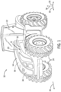
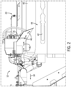
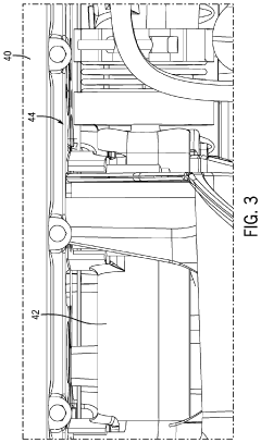
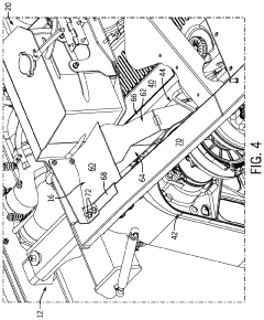
Engine airflow adjustment system
PatentActiveUS10688861B1
Innovation
- An engine airflow adjustment system that includes a funnel to redirect and focus airflow from the engine fan to specific locations, using angled sidewalls and a front wall to concentrate airflow and prevent debris from settling or becoming lodged in crevices, thereby blocking and removing debris from these areas.
Control device for engine
PatentInactiveJP2003193888A
Innovation
- The system uses intake pressure sensors to calculate fuel injection amounts until the engine stabilizes, transitioning to airflow sensor calculations after a predetermined period, with gradual weighting adjustments based on engine conditions to ensure accurate air-fuel ratio control.


Emissions Compliance Impact on Airflow Design
Emissions regulations have become increasingly stringent worldwide, fundamentally reshaping the approach to engine airflow design in the LT1 engine platform. The Environmental Protection Agency (EPA) Tier 3 standards and European Euro 6d regulations have established unprecedented requirements for reduced NOx, particulate matter, and CO2 emissions, directly impacting airflow optimization strategies. These regulations have necessitated a paradigm shift from purely performance-focused airflow designs to balanced solutions that maintain power while minimizing emissions.
The integration of emissions control systems has created significant challenges for airflow optimization. Exhaust Gas Recirculation (EGR) systems, now standard on the LT1 platform, introduce recirculated exhaust gases into the intake airflow, diluting the oxygen content and reducing combustion temperatures to control NOx formation. This recirculation fundamentally alters the intake airflow characteristics, requiring sophisticated flow modeling to maintain optimal combustion efficiency while meeting emissions targets.
Catalytic converter placement has emerged as a critical design constraint affecting exhaust airflow. The need for rapid catalyst light-off to reduce cold-start emissions has pushed converters closer to the exhaust manifold, creating potential flow restrictions and backpressure issues. Engineers working on the LT1 platform have developed innovative manifold designs with integrated catalysts that minimize flow disruption while maximizing thermal efficiency for emissions control.
Particulate matter regulations have driven the implementation of Gasoline Particulate Filters (GPFs) in many markets, adding another layer of complexity to exhaust airflow management. These systems create additional backpressure that must be accounted for in the overall airflow design. Computational Fluid Dynamics (CFD) modeling has become essential in predicting and mitigating the impact of these filtration systems on engine performance and efficiency.
The requirement for On-Board Diagnostics (OBD) systems to monitor emissions compliance has led to the integration of multiple sensors throughout the airflow path. These sensors must be positioned to accurately measure critical parameters without disrupting optimal airflow patterns. The placement of oxygen sensors, mass airflow sensors, and pressure transducers requires careful consideration of both measurement accuracy and flow disruption minimization.
Real-world emissions testing protocols, such as Real Driving Emissions (RDE) tests in Europe, have expanded the operating conditions under which emissions compliance must be maintained. This has necessitated airflow designs that perform optimally across a much wider range of engine loads, speeds, and environmental conditions than previously required, significantly increasing the complexity of the optimization challenge for LT1 engine development teams.
Thermal Management Considerations in Airflow Systems
Thermal management represents a critical aspect of LT1 engine airflow optimization, directly impacting both performance and longevity. The heat generated during combustion processes must be effectively managed to prevent component degradation and maintain optimal operating conditions. In the LT1 engine architecture, thermal considerations influence numerous design decisions related to airflow pathways, material selection, and cooling system integration.
Primary heat sources within the LT1 engine include combustion chambers, exhaust manifolds, and friction points between moving components. Without proper thermal management, these areas can experience temperature extremes leading to thermal expansion, material fatigue, and potential failure. Advanced computational fluid dynamics (CFD) modeling has revealed that optimized airflow patterns can reduce localized hotspots by up to 15-20%, significantly extending component lifespan.
The integration of thermal sensors throughout the airflow system provides real-time temperature monitoring, enabling adaptive control strategies. These sensors communicate with the engine management system to adjust airflow parameters based on thermal conditions, creating a dynamic response to varying operational demands. Recent developments in thermal barrier coatings have shown promising results in isolating critical components from excessive heat exposure while maintaining efficient heat transfer where beneficial.
Material selection plays a crucial role in thermal management within airflow systems. High-temperature alloys and composite materials with superior thermal properties are strategically implemented in areas experiencing extreme temperature fluctuations. These materials offer enhanced durability while minimizing thermal expansion issues that could compromise airflow geometry during operation.
Cooling channel design represents another vital consideration in LT1 airflow optimization. The strategic placement of cooling passages must balance adequate heat dissipation with minimal disruption to primary airflow paths. Research indicates that optimized cooling channel geometry can improve thermal efficiency by approximately 8-12% compared to conventional designs, while simultaneously reducing parasitic power losses associated with cooling systems.
Heat exchanger technology has evolved significantly, with compact, high-efficiency designs now capable of managing thermal loads more effectively than previous generations. These systems work in concert with airflow optimization to ensure that heat is transferred away from critical components at rates matching or exceeding heat generation during peak operation conditions.
The relationship between thermal management and overall engine efficiency cannot be overstated. Properly managed thermal conditions enable more precise combustion timing, reduced friction losses, and optimized air density throughout the intake system. These factors collectively contribute to improved power output, fuel efficiency, and emissions performance in the LT1 engine platform.
Unlock deeper insights with PatSnap Eureka Quick Research — get a full tech report to explore trends and direct your research. Try now!
Generate Your Research Report Instantly with AI Agent
Supercharge your innovation with PatSnap Eureka AI Agent Platform!