Automatic hot-cutting side gate injection mold, and gate cutter and injection molding process thereof

A technology of side gate and injection mold, which is applied in the field of automatic hot-cut side gate injection mold, gate cutter and injection molding process, can solve the problems of low lifespan and residual gate cutting surface, so as to save mold cost, The effect of reducing maintenance cost and optimizing processing progress

Active Publication Date:
View PDF8 Cites 2 Cited by
  • Summary
  • Abstract
  • Description
  • Claims
  • Application Information

AI Technical Summary

Problems solved by technology

[0008] The purpose of the present invention is to overcome the residual defects of the gate cutting surface in the existing automatic hot-cut side gate injection mold, and provide a new automatic hot-cut side gate injection mold. The technical problem to be solved is to make it It can meet high-speed automatic production, and can complete the in-mold gate shearing of complex products with high appearance requirements, no residue in the incision, and no subsequent secondary processing
[0009] One object of the present invention is to overcome the defects that the mold and the gate cutter exist in the existing automatic hot-cut side gate injection mold due to collision, and the lifespan is not high, and provide a gate cutter to improve the cutting efficiency of the mold and the gate. knife life

Method used


Image

  • Automatic hot-cutting side gate injection mold, and gate cutter and injection molding process thereof
  • Automatic hot-cutting side gate injection mold, and gate cutter and injection molding process thereof
  • Automatic hot-cutting side gate injection mold, and gate cutter and injection molding process thereof

Examples


Embodiment Construction

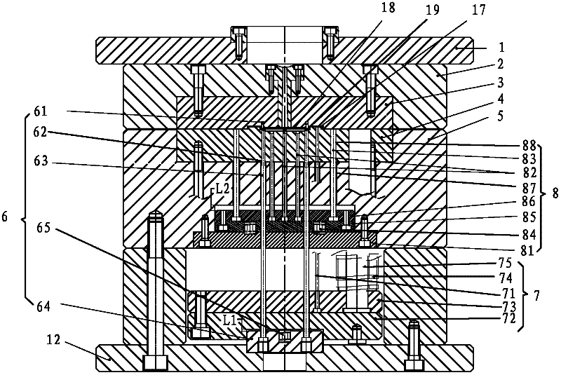
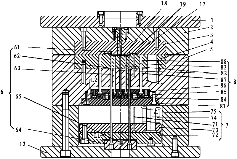
[0037] In order to further explain the technical means and effects that the present invention takes to achieve the intended invention purpose, below in conjunction with the accompanying drawings and preferred embodiments, the automatic hot-cut side gate injection mold proposed according to the present invention, the used gate cutter and injection molding Process, its specific implementation, steps, structure, features and effects thereof are as follows in detail.

[0038] see figure 1 , as shown, a kind of automatic hot-cutting side gate injection mold of the preferred embodiment of the present invention, comprises the front mold fixing plate 1 that is arranged in sequence, the front mold core 3, the front template 2 that fixes described front mold core 3, rear The mold core 4, the back template 5 for fixing the rear mold core 4, the rear mold fixing plate 12 with a push hole, the part cavity 17 and the sprue are formed between the front mold core 3 and the rear mold core 4 1...


PUM


Abstract

The invention relates to an injection mold, in particular to an automatic hot-cutting side gate injection mold. The injection mold comprises a front mold fixing plate, a front mold core, a front mold plate, a rear mold core, a rear mold plate which is used for fixing the rear mold core and a rear mold fixing plate which is provided with a pushing hole, wherein the front mold plate and the rear mold core are used for fixing the front mold core; a part cavity, a pouring channel and a gate are formed between the front mold core and the rear mold core; and a gate shearing device and a product push-out device are arranged below the rear mold plate. The injection mold is characterized in that: a material handle push-out device is arranged on the rear mold plate; the product push-out device is arranged between the rear mold plate and the rear mold fixing plate; the gate shearing device is arranged between the product push-out device and the rear mold fixing plate; and the material handle push-out device is arranged on the rear mold plate. The automatic hot-cutting side gate injection mold is suitable for producing injection molding products which have complicated shapes and strict appearance requirements; and residues do not exist at an incision, subsequent secondary machining is not required, the mold is not required to be maintained and welded, and a gate cutter has long service life.

Description

technical field [0001] The invention relates to an injection mold, in particular to an automatic mold which is suitable for injection molding production with complex shapes and strict appearance requirements, and has no residue in the cut, no need for subsequent secondary processing, no need for maintenance and welding of the mold, and long service life of the gate cutter. Hot cut side gate injection mold, gate cutter used and injection molding process. Background technique [0002] At present, most injection molding parts are produced by side-feeding two-plate molds. The advantages of side-feeding are uniform glue feeding, no punch marks, and low internal stress of the product, but the disadvantages are cumbersome post-processing and many people. In order to solve the problem of cumbersome secondary processing and reduce labor costs while using side glue ports, in-mold automatic cold cutting is often used. This method can only be used for products with simple structures and...

Claims


Application Information

Patent Timeline
Patent Type & Authority Applications(China)
IPC IPC(8): B29C45/26B29C45/38B29C45/40
Inventor 何雄刘惠林石磊刘时元刘安培
Why Eureka
Try Eureka