Small ball trajectory demonstrating device

A demonstration device and small ball technology, which is applied in the direction of educational appliances, instruments, teaching models, etc., can solve the problem of being unable to observe the gravitational potential energy of the small ball into electrical energy, unable to independently change the trajectory of the small ball, and unable to observe the movement of the small ball Process and other issues, to achieve the effect of easy understanding and learning, clear energy conversion process, simple and novel structure

Inactive Publication Date: 2017-01-04
JIANGSU HUAMING SCI & EDUCATION EQUIP
View PDF24 Cites 5 Cited by
  • Summary
  • Abstract
  • Description
  • Claims
  • Application Information

AI Technical Summary

Problems solved by technology

[0004] However, in this structure, first, the trajectory of the demonstration ball is single, and it is impossible to change the trajectory of the ball independently; second, it is impossible to observe the dynamic changes of the ball on the roller coaster; third, it is impossible to observe the vertical upward movement of the ball The dynamic changes of throwing and falling; 4. The dynamic changes of the ball sliding down the slope cannot be observed; 5. The process of the ball hitting the gong through the lever cannot be observed; 6. The ball rotating and falling in the funnel cannot be observed Seventh, it is impossible to observe the movement process of the ball hitting the drum surface and rebounding; Eighth, it is impossible to observe the process of converting the gravitational potential energy of the small ball into electrical energy

Method used


Image

  • Small ball trajectory demonstrating device
  • Small ball trajectory demonstrating device
  • Small ball trajectory demonstrating device

Examples


Embodiment Construction

[0075] The present invention will be further described in detail below in conjunction with the accompanying drawings, so that those skilled in the art can implement it with reference to the description.

[0076] It should be understood that terms such as "having", "comprising" and "including" as used herein do not entail the presence or addition of one or more other elements or combinations thereof.

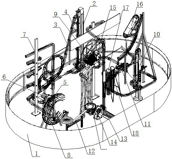
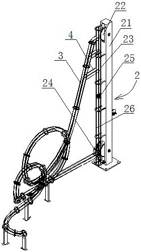
[0077] Figures 1 to 5 It shows an implementation form according to the present invention, which includes: a booth 1, on which a lifting device 2 is installed, and the lifting device 2 has a vertical rod 21, and the two ends of the vertical rod 21 are respectively rotated to install gears 22, two gears 22 is connected to the chain 23 by transmission, and one of the gears 22 is connected to the stepper motor 24. The chain 23 is vertically fixed on the supporting plate 25, and the vertical bar 21 is vertically fixed on the booth 1. Along the vertical bar 21 One side is fixed to pr...


PUM


Abstract

The invention discloses a small ball trajectory demonstrating device, which comprises a lifting device and a roller coaster, wherein the lifting device is provided with a vertical rod; gears are arranged at two ends of the vertical rod in a rotary mode; a chain is in transmitted connection between the two gears; one of the gears is in transmitted connection with a stepping motor; a supporting plate is fixedly arranged on the chain; the roller coaster stretches along a fluctuated tubular rail which is formed by connecting a plurality of lines; the roller coaster stands on an exhibition stand, wherein an anti-falling rail is fixed along one side of the vertical rod, and the chain and the supporting plate can transmit in the rail; the rail at the highest point of the lifting device communicates with the starting end of the roller coaster; and the rail at the lowest point of the lifting device communicates with the ending end of the roller coaster. With the application of the small ball trajectory demonstrating device disclosed by the invention, the states of an object in a circular motion and a downhill linear motion can be observed; and the small ball trajectory demonstrating device, which adopts one-key operation, is high in automation degree, simple to operate and is time-saving and labor-saving, and the small ball trajectory demonstrating device is capable of conducting demonstration repeatedly and is capable of improving a demonstrating effect.

Description

technical field [0001] The present invention relates to a device used in scientific and educational experiments and recreational activities. More specifically, the present invention relates to a small ball trajectory demonstration device for scientific and educational experiments. Background technique [0002] As we all know, the small ball trajectory demonstrator is used to display the dynamic changes of small ball physics in scientific and educational experiments and entertainment activities, which is convenient for studying the dynamic change characteristics and energy conversion of objects, making the whole teaching process more vivid and interesting, and easy for students to understand and accept . [0003] Specifically, the small ball trajectory demonstrator usually includes the following structures: a small ball for trajectory demonstration, a lifting device for promoting the height of the small ball, an inclined track, a vertical track and a circuitous track, by l...

Claims


Application Information

Patent Timeline
IPC IPC(8): G09B23/10
CPCG09B23/10
Inventor 袁宝成纪建科
Owner JIANGSU HUAMING SCI & EDUCATION EQUIP
Why Eureka
Try Eureka