Pipeline barrier clearance patrol device

A technology for clearing obstacles and pipelines, which is applied in the field of pipeline obstacle-clearing inspection devices, can solve the problems of extended construction period, increased obstacle-clearing time, and increased conveyor power, so as to shorten the time of obstacle-clearing, improve the efficiency of obstacle-clearing, and improve The effect of movement speed

Pending Publication Date: 2020-08-14
温州电力建设有限公司 +1
View PDF0 Cites 0 Cited by
  • Summary
  • Abstract
  • Description
  • Claims
  • Application Information

AI Technical Summary

Problems solved by technology

The laying period of a cable duct with a length of 100 meters is required to be no more than 8 hours, of which the time for pulling the cable by the conveyor takes up 7 hours. Considering that the preparation work takes 30 minutes, the time left for inspection and clearance should not exceed 30 minutes, otherwise it will cause The construction period is extended, but the existing iron cylindrical pigs are used in the cleaning work, and a traction line is attached to one end, and the conveyor is pulled from the end of the cable shaft. Due to the heavy weight of the iron cylindrical pigs, it is necessary to A large traction force is used to pull it to carry out the obstacle removal work, thereby increasing the power of the conveyor, and the iron cylindrical pig moves slowly, thus increasing the obstacle removal time. In addition, the existing obstacle cleaner can only Carry out obstacle removal treatment on the pipeline, so that it is impossible to obtain the foreign matter in the pipeline in real time when the obstacle remover is working, which is not conducive to the obstacle removal work of the obstacle remover, thereby reducing the quality of the obstacle removal device

Method used


Image

  • Pipeline barrier clearance patrol device
  • Pipeline barrier clearance patrol device
  • Pipeline barrier clearance patrol device

Examples


Embodiment Construction

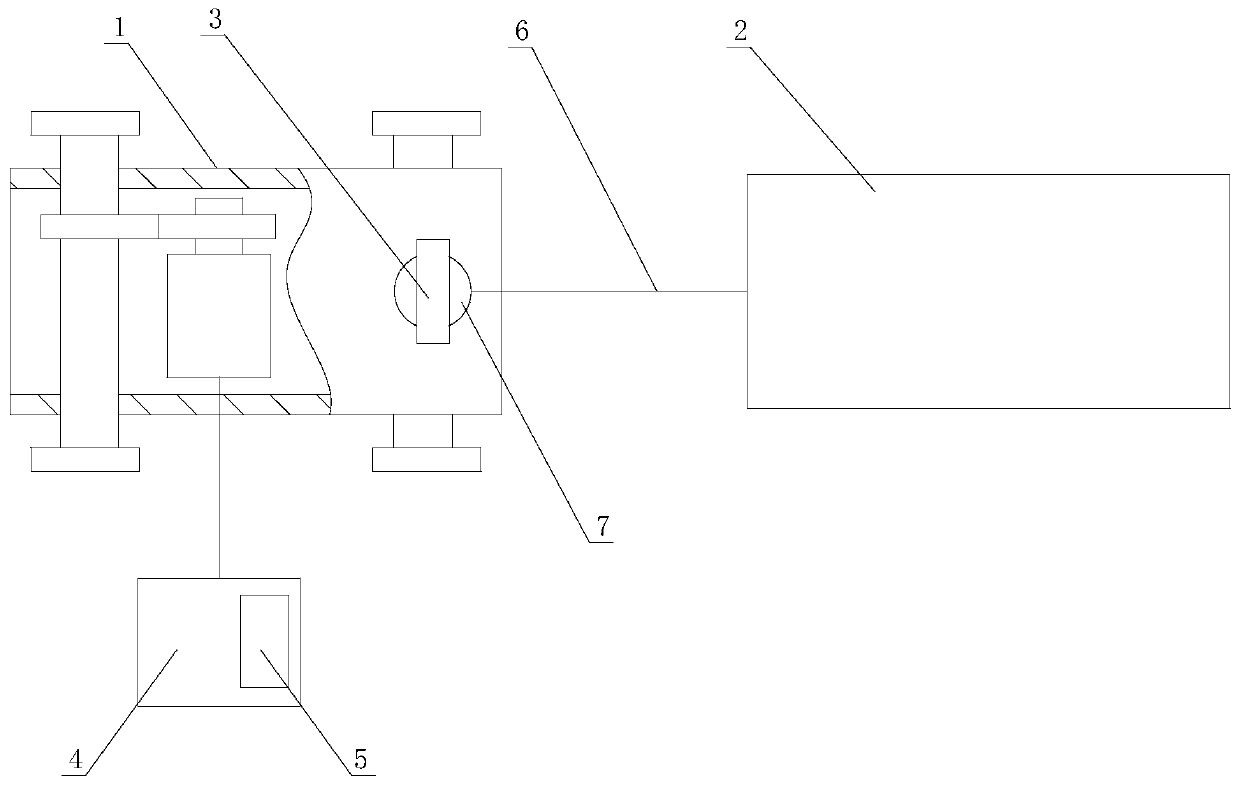
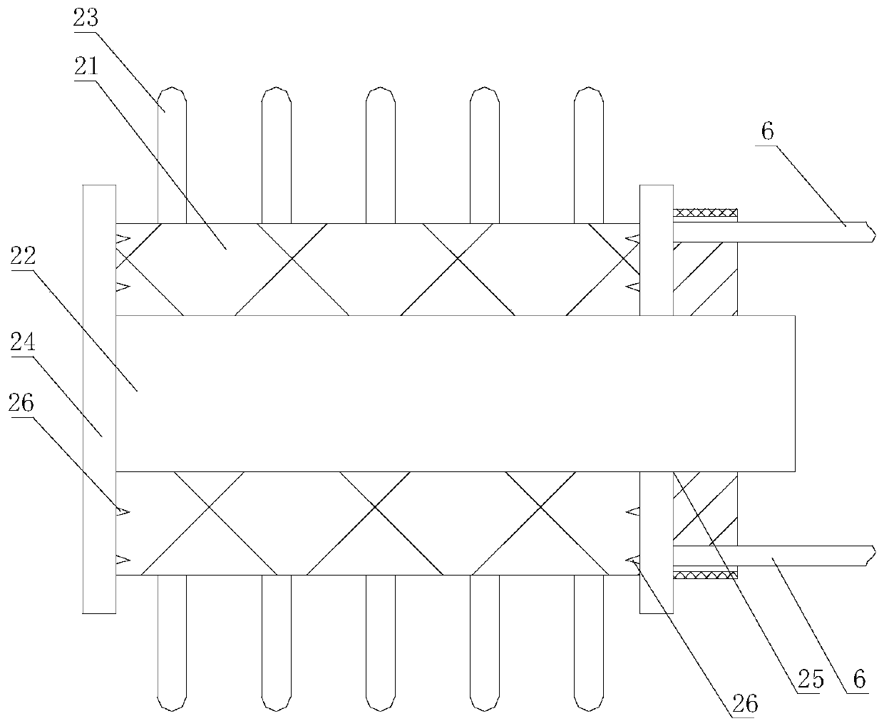
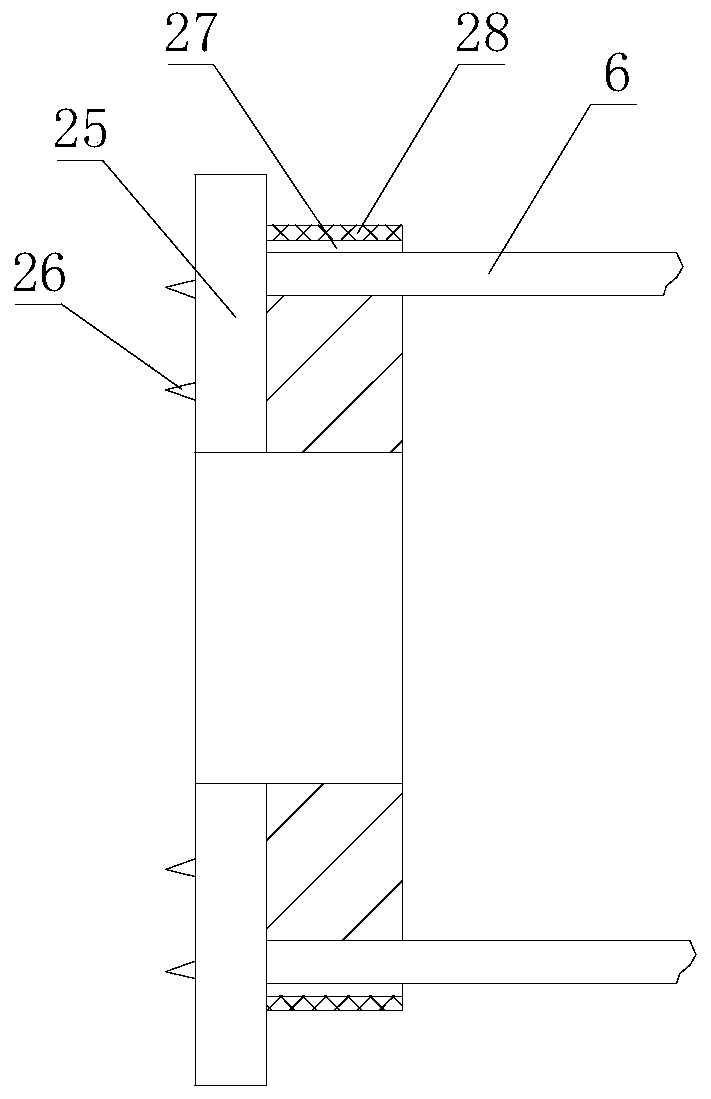
[0024] like figure 1 , figure 2 , image 3 , Figure 4 , Figure 5 , Image 6 As shown, a pipeline obstacle removal inspection device includes a walking assembly 1 and an obstacle removal assembly 2. The obstacle removal assembly 2 includes a polyurethane sleeve 21, and the polyurethane sleeve 21 is detachably mounted on the walking On the assembly 1, the walking assembly 1 is also provided with a camera assembly 3, and the walking assembly 1 is also connected with a control assembly 4 that controls the movement of the walking assembly 1, and the control assembly 4 is provided with a camera assembly 3 that links to each other. Show component 5.

[0025] The camera assembly 3 on the walking assembly 1 carries out imaging processing to the pipeline, so the pipeline can be imaged during the walking assembly 1 walking process, and receives the image information captured by the imaging assembly 3 in real time through the display assembly 5. Next, the walking process In the p...


PUM


Abstract

The invention relates to a pipeline barrier clearance patrol device which comprises a walking component and a barrier clearance component; the barrier clearance component comprises a polyurethane sleeve; the polyurethane sleeve is detachably mounted on the walking component; a camera shooting component is further arranged on the walking component; a control component controlling the walking component to act is connected onto the walking component; and a display component connected with the camera shooting component is arranged on the control component. The pipeline barrier clearance patrol device has the following advantages: the camera shooting component on the walking component carries out camera shooting treatment on a pipeline, came shooting treatment can be carried out on the pipelineduring the walking process of the walking component, the display component receives the image information shot by the camera shooting component in real time, and then, the barrier clearance componentcarries out barrier clearance on the pipeline during the walking process, so that barrier clearance and checking can be simultaneously carried out during the barrier clearance process, and the in-pipeline checking time does not need to be additionally occupied to greatly shorten the barrier clearance time.

Description

technical field [0001] The invention relates to a pipeline obstacle removal inspection device. Background technique [0002] Cables need to be laid during the construction of substations and power lines. Before pulling the cables, the pipeline must be cleared. After checking that there is no debris in the pipelines, the cables can be laid. Therefore, the cable laying process is preparation work, obstacle removal and pulling cables. , Before pulling the cable, it is necessary to check whether the clearing work is completed. When the clearing is not completed, it is necessary to continue the clearing work. According to the construction requirements and process restrictions, the length of one-time laying shall not exceed 100m. The laying period of a cable duct with a length of 100 meters is required to be no more than 8 hours, of which the time for pulling the cable by the conveyor takes up 7 hours. Considering that the preparation work takes 30 minutes, the time left for inspe...

Claims


Application Information

Patent Timeline
Patent Type & Authority Applications(China)
IPC IPC(8): F16M11/04F16M11/08F16M11/42B08B9/047B08B13/00H04N5/225
CPCF16M11/046F16M11/08F16M11/42B08B9/047B08B13/00H04N23/50
Inventor 游亦强曾璧环潘益伟孔凡坊刘尚孟金琰斌张翼王珠峰王瑞林珑罗涛李云龙
Owner 温州电力建设有限公司
Why Eureka
Try Eureka