
Mounting structure of intelligent air conditioner outdoor unit
A technology of intelligent air conditioning and installation structure, applied in air conditioning system, space heating and ventilation, cleaning method using tools, etc., can solve the problems of loose bolts, lack of cleaning mechanism, lack of height adjustment mechanism of installation structure, etc. risk of falling, improved ventilation, improved flexibility
Patent Information
- Authority / Receiving Office
- CN · China
- Patent Type
- Applications(China)
- Current Assignee / Owner
- Publication Date
- 2020-10-30
Smart Images
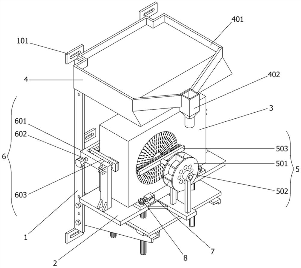
Figure 1 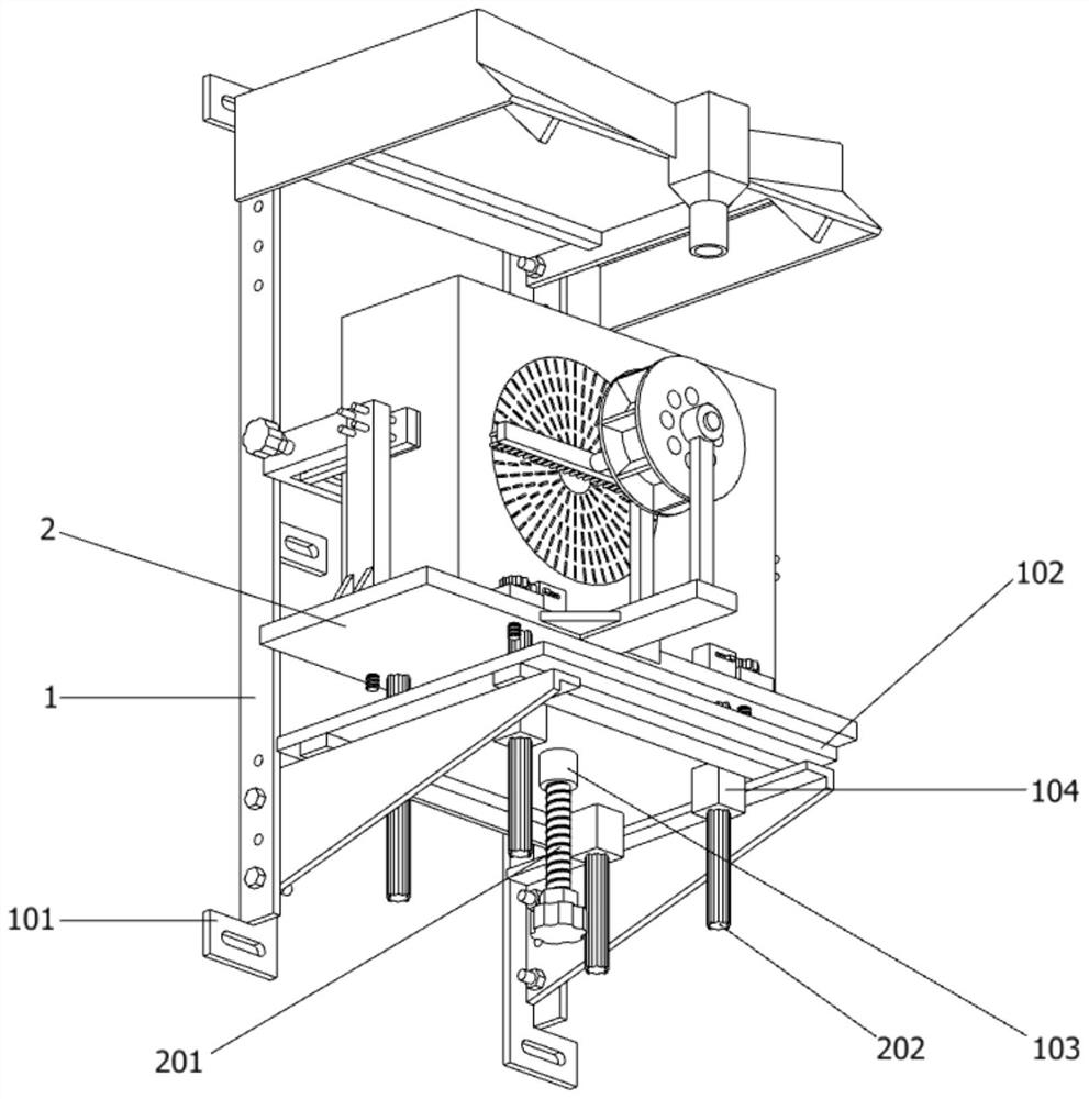
Figure 2 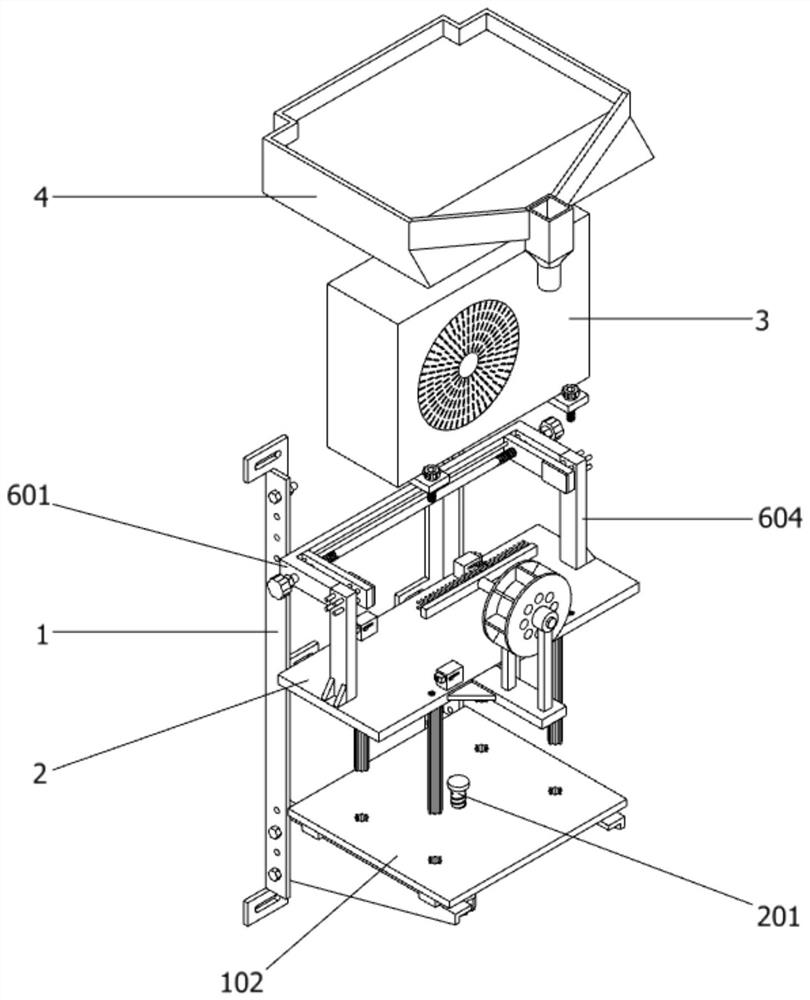
Figure 3
Abstract
Description
technical field
[0001] The invention belongs to the technical field of installation structure, and more specifically relates to an installation structure of an intelligent air conditioner external unit. Background technique
[0002] A smart air conditioner is an air conditioner with an automatic adjustment function. The intelligent air conditioning system can analyze and judge the signals sent by the temperature, humidity, and air cleanliness sensors according to the external climate conditions and according to the preset indicators, and automatically turn on the air conditioners with functions such as cooling, heating, dehumidification and air purification in time. .
[0003] For example, the application number: CN201210374109.2 The present invention relates to a vibration isolation installation structure of an air conditioner external unit, which is installed on the outer wall of a room and consists of a vibration isolation installation frame and a position-limiting balan...
Examples
Embodiment
[0034] as attached figure 1 To attach Figure 9 Shown:
[0035] The invention provides an installation structure of an intelligent air conditioner outdoor unit, which includes: an angle steel installation frame 1, a height adjustment mechanism 2 is provided on the front side of the angle steel installation frame 1, and the height adjustment mechanism 2 includes an adjustment screw 201, a square sliding column 202, a disc Type connecting block 203 and rectangular support plate 204, a disc-shaped connecting block 203 is provided at the center of the bottom end surface of the height adjustment mechanism 2, and a T-shaped card slot is provided at the center of the bottom end surface of the disc-shaped connecting block 203, and the disc-shaped connection The inside of the block 203 is rotatably connected with an adjusting screw 201 through a T-shaped slot, and the upper end of the adjusting screw 201 is provided with a T-shaped block that is rotatably connected with the T-shaped s...