Method for pre-stressed reinforcing concrete compression member

A compression component and prestressing technology, which is applied in building construction, building maintenance, construction, etc., can solve the problems of force transmission plate thickness error, large cumulative error, and complicated construction technology, so as to reduce the stress level of the original structure and improve The total bearing capacity of the structure, the effect of eliminating strain hysteresis

A compression component and prestressing technology, which is applied in building construction, building maintenance, construction, etc., can solve the problems of force transmission plate thickness error, large cumulative error, and complicated construction technology, so as to reduce the stress level of the original structure and improve The total bearing capacity of the structure, the effect of eliminating strain hysteresis

CN1401873AInactive Publication Date: 2003-03-12杜旌 +2

Image

  • Method for pre-stressed reinforcing concrete compression member
  • Method for pre-stressed reinforcing concrete compression member
  • Method for pre-stressed reinforcing concrete compression member

Examples


Embodiment Construction

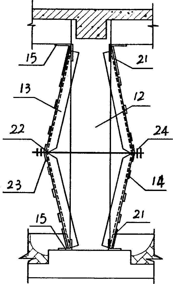
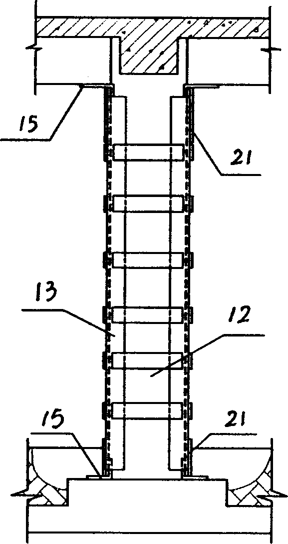
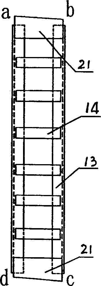
[0083] Such as Image 6 , Figure 7 , Figure 8, Figure 9, Figure 10, and Figure 11, the method of prestressing concrete compression members is divided into five steps: 1) Prestress calculation, 2) Jack torsion calculation, 3) Outsourcing strut angle steel and jack installation, 4) prestressing, 5) fixing and jack removal. 1), prestress calculation

[0084] a. Axial Force Calculation

[0085] (1) Determine the full axial compressive bearing capacity N to be borne after reinforcement;

[0086] (2) According to the current "Code for Design of Concrete Structures" (GBJ10-89), calculate the axial compressive bearing capacity of the original reinforced concrete N 0 :

[0087] N 0 =(A co f co +A' so f' yo ) (4.1) where n 0 ——the axial compressive bearing capacity of the original column;

[0088] ——coefficient of stability of original column;

[0089] A co - the cross-sectional area of ​​the original column;

[0090] f co — design value of concrete compressive s...


PUM


Abstract

A method for reinforcing the concrete member by prestress includes such steps as calculating prestress and the torsion force of jack, installing supporting angle steel and jack, applying prestress, fixing, and detaching jack. Its advantages are high reinforcing effect on increasing total bearing power, high correctness of prestress, and easy control.

Description

technical field [0001] The invention relates to a method for strengthening concrete compression components, in particular to a method for prestressing concrete compression components. Background technique [0002] Reinforced concrete structure is the most widely used structure in engineering construction all over the world, and its development and application has a history of more than 100 years. However, during the use of concrete structures, concrete members will continue to be damaged and aged over time, and their bearing capacity, stiffness, ductility and stability will continue to decline, so the branch of concrete structure reinforcement emerged in the 1960s. [0003] At present, there are many reinforcement methods commonly used in actual engineering, such as enlarging section method, replacement method, prestressing method, increasing fulcrum method, outsourcing steel reinforcement method, bonded steel reinforcement and viscose fiber cloth method, etc. 1. Stress cha...

Claims


Application Information

Patent Timeline
12 Mar 2003
Publication
CN1401873A
IPC
E04B1/20; E04G23/02; E04G23/04
Inventors
杜旌; 李冠峰