
Vehicle drive assist system
a technology for assist systems and vehicles, applied in brake systems, navigation instruments, instruments, etc., can solve the problems of limited visibility in the backward area of the vehicle, driver's care, and limit in perfectly grasping the environmental conditions, etc., and achieve the effect of simple voice system and simple image display
Patent Information
- Authority / Receiving Office
- US · United States
- Patent Type
- Applications(United States)
- Current Assignee / Owner
- Publication Date
- 2006-12-21
- Estimated Expiration
- Not applicable · inactive patent
Smart Images
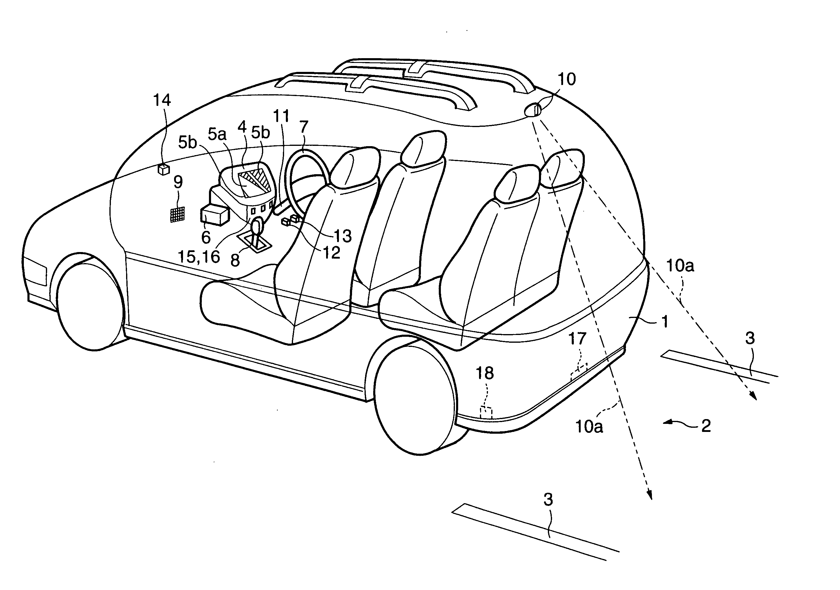
Figure 1 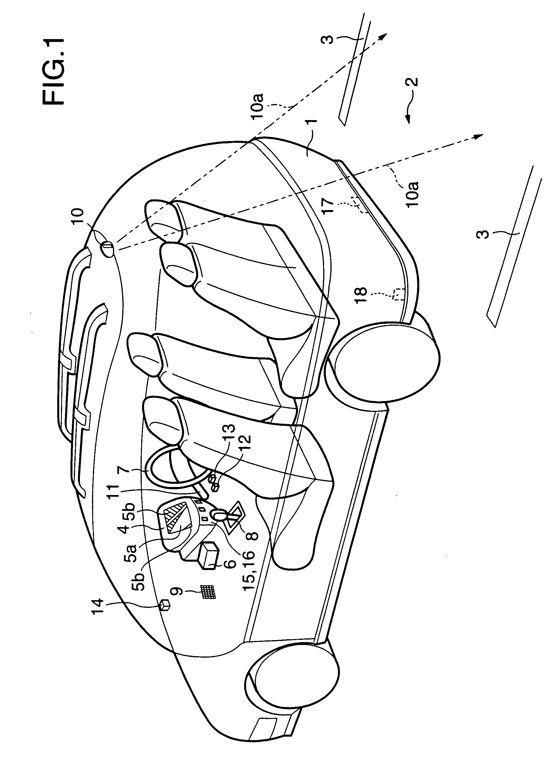
Figure 2 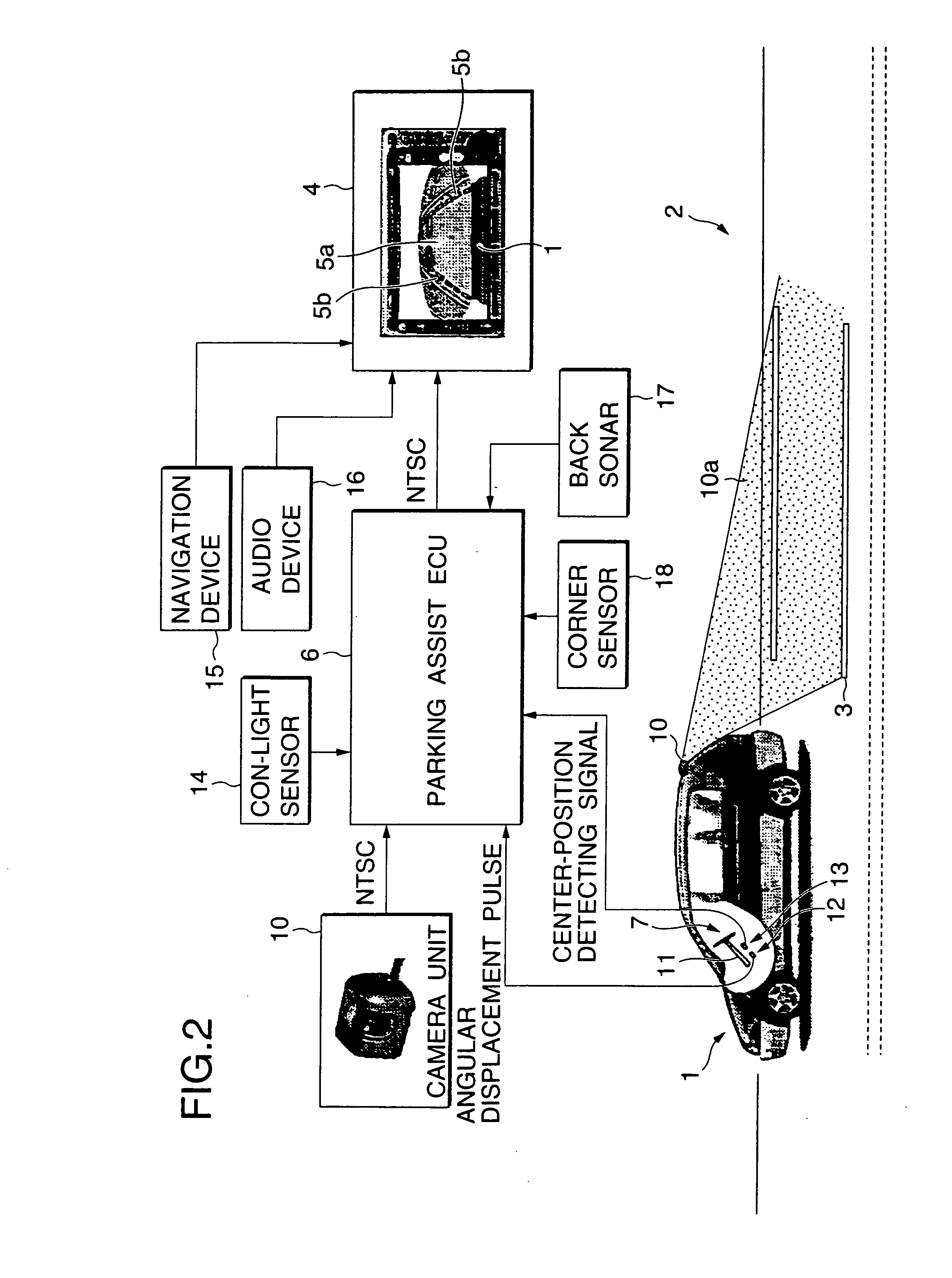
Figure 3
Abstract
Description
[0001] This is a Division of application Ser. No. 09 / 598,270 filed Jun. 21, 2000. The disclosure of the prior application is hereby incorporated by reference herein in its entirety.BACKGROUND OF THE INVENTION
[0002] 1. Field of the Invention
[0003] The present invention relates to a vehicle parking assist device for assisting a driver in his driving by use of an image obtained by taking a scene of an area around a vehicle.
[0004] 2. Description of the Related Art
[0005] To drive a vehicle, e.g., automobile, in safety, the driver needs to look traffic conditions around the vehicle attentively. The driver constantly watches the environment of the vehicle and makes efforts to grasp environmental conditions of the vehicle, while driving the vehicle. When the grasping effort depends on only the sense, there is a limit in perfectly grasping the environmental conditions. The human visual sensation is very important in grasping the environmental conditions. However, it is effective only in ...
Examples
first embodiment
[0366]FIGS. 1 and 2 are diagrams showing a scheme of a vehicle parking assist device which is the present invention. Like reference numerals are used, for simplicity, for designating like or equivalent portions through the drawings which will be referred to in the description of the preferred embodiments of the invention.
[0367] The vehicle parking assist device of the embodiment assists the driver to correctly park a vehicle into a parking space marked off with white lines 3 or the like, through the backward movement of the vehicle. A drive assist displays a predictive traveling path curve 5a representing as a predictive traveling path on the screen of an information display device 4 as display means, or white lines 5b prolonged from the lines demarcating both sides of a vehicle 1 on the display screen, whereby a drive assist for the driver is performed.
[0368] The predictive traveling path curve 5a and the white lines 5b are generated by an electronic control unit (referred to as a...
third embodiment
[0397]FIG. 10 shows a scheme of a vehicle parking assist device which is the invention. In the embodiment, a plan model 60 is provided to select a series parking mode for a series parking assist 61 or a normal parking mode for a normal parking assist 62 on the screen of the information display device 4. In the normal parking mode, the field 50a of the camera unit 50 and the illumination by the back light 52 are directed mainly to the backward area of the vehicle 1. In the series parking mode, the field 50a of the camera unit 50 and the illumination by the back light 52 are directed to the side of the vehicle.
[0398] The series parking mode or the normal parking mode may be automatically selected. The series parking mode may be selected when the turning on of the winker lamp 63 or the hazard lamp 64 and the shifting of the shift lever 8 to the reverse gear position are simultaneously performed. In an alternative, the driver refers to map data about the present position of the vehicle ...
fourth embodiment
[0399]FIG. 11 is a diagram showing the invention. In the embodiment, a plurality of camera units 10 are arranged around the body of a vehicle 1. Images output from those camera units 10 are simultaneously displayed on the same screen of the information display device. As shown, the camera units 10 are located at the front left L, the front right R and the back B of the vehicle 1. Each camera unit picks up a scene within the field 10a thereof.
[0400] Each of FIGS. 12(1) to 12(12) exemplarily shows segmented display areas formed by segmenting the screen of the information display device 4. The images output from the plurality of the camera units 10 are simultaneously displayed in those display areas, respectively. Where those areas are used, all the images may be watched on one screen. In the example of FIG. 12(1), the screen is segmented in a time divisional manner, and only the image of the backward area is displayed. The screen is automatically changed at fixed time intervals to dis...