
Electronic aircraft braking system with brake wear measurement, running clearance adjustment and plural electric motor- actuator ram assemblies
a technology of actuator rams and actuators, applied in the field of electronic aircraft braking systems, can solve the problems of inherently imprecise, increased running clearance of actuator rams, and devices adding weight and complexity to the braking system
Patent Information
- Authority / Receiving Office
- US · United States
- Patent Type
- Applications(United States)
- Current Assignee / Owner
- Publication Date
- 2007-06-07
- Estimated Expiration
- Not applicable · inactive patent
Smart Images
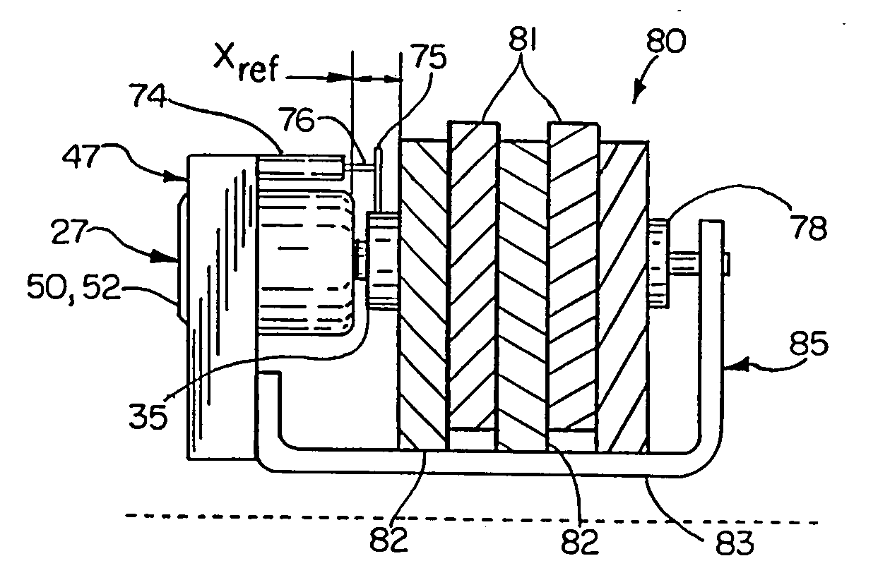
Figure 1 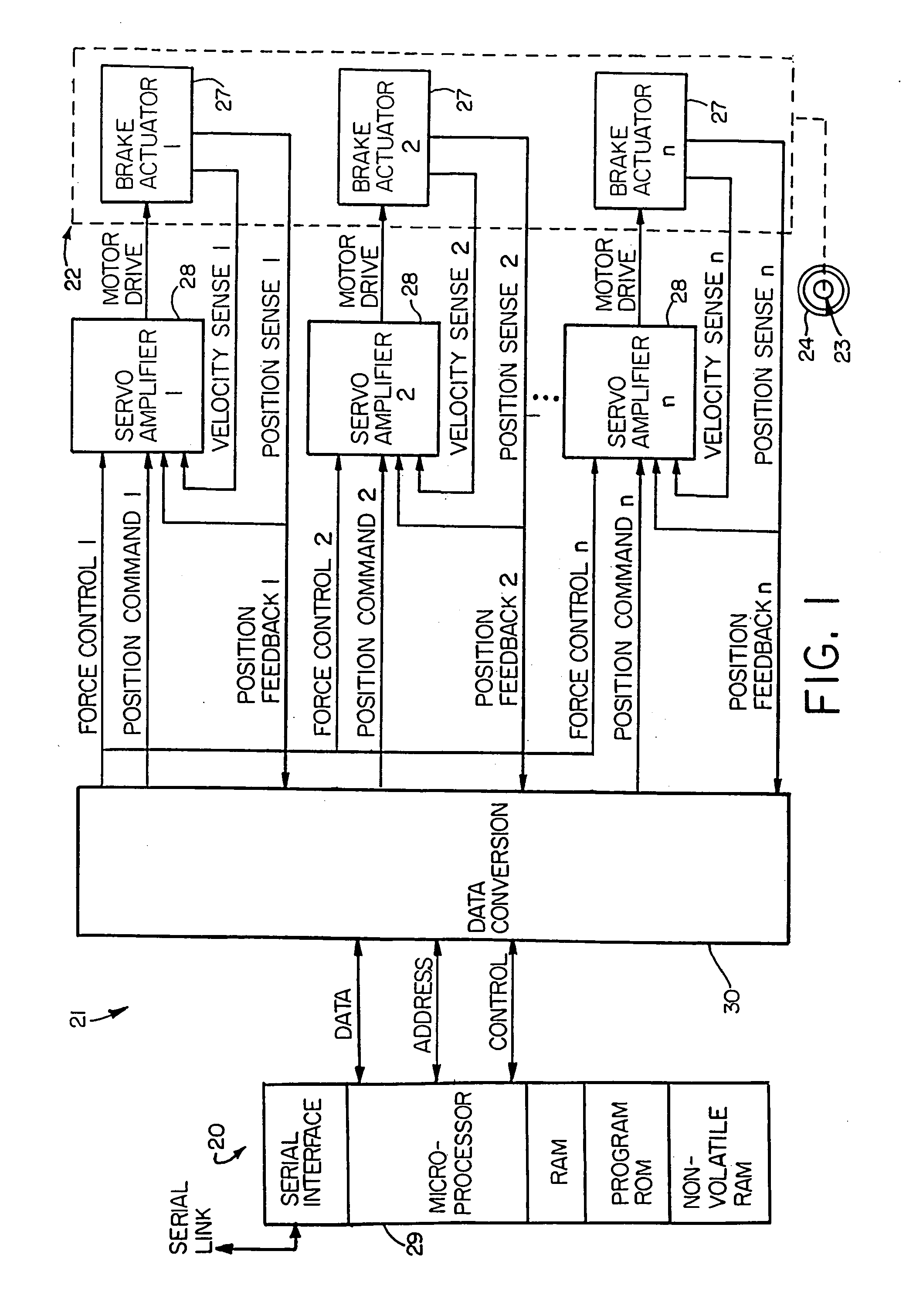
Figure 2 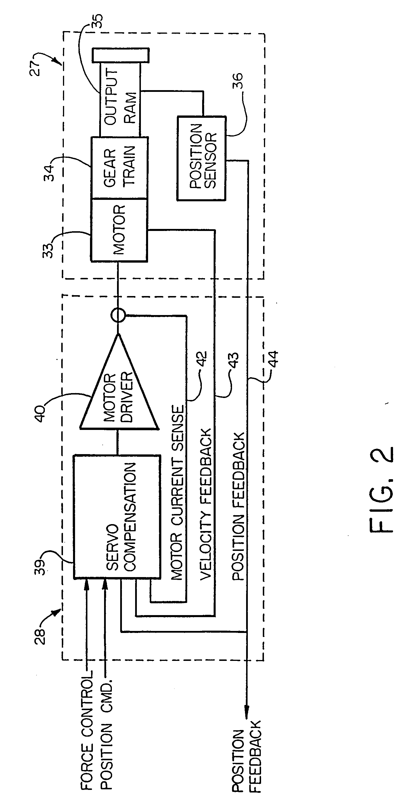
Figure 3
Abstract
Description
RELATED APPLICATION DATA
[0001] This application is a continuation of U.S. patent application Ser. No. 10 / 796,776 filed Mar. 9, 2004, which is a continuation of U.S. patent application Ser. No. 10 / 268,409 filed Oct. 10, 2002, which is a continuation of U.S. patent application Ser. No. 09 / 486,687, filed Mar. 1, 2000, which is a continuation-in-part of U.S. patent application Ser. No. 08 / 853,513, filed May 9, 1997. The aforesaid applications are hereby incorporated herein by reference in their entireties.FIELD OF THE INVENTION
[0002] The invention herein described relates generally to brake control systems, more particularly to electronic braking systems, and still more particularly to aircraft braking systems. BACKGROUND OF THE INVENTION
[0003] Known in the prior art are aircraft wheel and brake assemblies including a non-rotatable wheel support, a wheel mounted to the wheel support for rotation, and a brake disk stack having front and rear axial ends and alternating rotor and stator...
Examples
Embodiment Construction
[0041] Referring now in detail to the drawings, FIG. 1 diagrammatically illustrates an exemplary multi-actuator computer controlled brake actuation system 20 to which the principles of the invention may be applied. The major functions of the system 20 are performed by a controller 21 and a brake actuator assembly 22. The brake actuator assembly 22 may be mounted in a conventional manner on a wheel and brake assembly 23 to apply and release braking force on a rotatable wheel 24 of such wheel and brake assembly. The present invention is particularly suited for use in aircraft braking systems, as will be appreciated by those skilled in the art.
[0042] Because the invention was conceived and developed for use in an aircraft braking system and particularly in association with the system 20, it will be herein described chiefly in this context. However, the principles of the invention in their broader aspects can be adapted to other types of systems including, for example, hydraulic system...