Image display device, image display method, program, and projection system

Inactive Publication Date: 2006-05-02
CASIO COMPUTER CO LTD
View PDF8 Cites 62 Cited by
  • Summary
  • Abstract
  • Description
  • Claims
  • Application Information

AI Technical Summary

Benefits of technology

[0015]According to this image display device, an image picked up by an image pickup section which is set in an arbitrary position is adequately displayed on a display screen. A picked-up spot is adequately displayed on the display screen after the position of the spot is converted by the coordinate conversion section. Accordingly, operational characteristic of this image display device is excellent.
[0038]According to this image display device, an image picked up by the image pickup section which is set in an arbitrary position is adequately displayed on the display screen. The picked up spot is adequately displayed on the display screen after the position of the spot is converted by the coordinate conversion section. The shape of a spot to be displayed reflects the position of the picked up spot. Accordingly, operational characteristic of this image display device is excellent.
[0073]According to a computer which executes this program, an image display device, and an image pickup section, an image picked up by the image pickup section placed at an arbitrary position is displayed on a display screen adequately. Further, a picked-up spot is displayed adequately on the display screen after the position of the spot is converted. Accordingly, operational characteristic when controlling a computer to display an image is excellent.
[0076]According to a computer which executes this program, an image display device, and an image pickup section, an image picked up by the image pickup section placed at an arbitrary position is displayed on a display screen adequately. Further, a picked-up spot is displayed adequately on the display screen after the position of the spot is converted. The shape of the spot to be displayed reflects the position of the picked-up spot. Accordingly, operational characteristic when controlling a computer to display an image is excellent.

Problems solved by technology

Otherwise, it is impossible to detect the position of the supplementary light appropriately.
Thus, the operator experiences the difficulty in operating the laser pointer, etc.
Further, it is difficult to set the image pickup device in the right position.
Especially, in a case where the optical system of the image pickup device causes aberration, it is extremely difficult to determine the right position.
Furthermore, if the positional relation between the image pickup device and the screen is fixed where the image pickup device is set in the right position, it is impossible to change the position of the image pickup device.
Thus, the image pickup device cannot be used for other purposes.

Method used


Image

  • Image display device, image display method, program, and projection system
  • Image display device, image display method, program, and projection system
  • Image display device, image display method, program, and projection system

Examples


first embodiment

[0159]Next, the operation of this drawing system will be explained with reference to FIG. 3 to FIG. 6.

[0160]FIG. 3 is a flowchart showing a drawing process.

[0161]FIG. 4 is a flowchart showing the image analysis process.

[0162]FIG. 5 is a flowchart showing the spotlight extraction process.

[0163]FIG. 6 is a flowchart showing the coordinate conversion process.

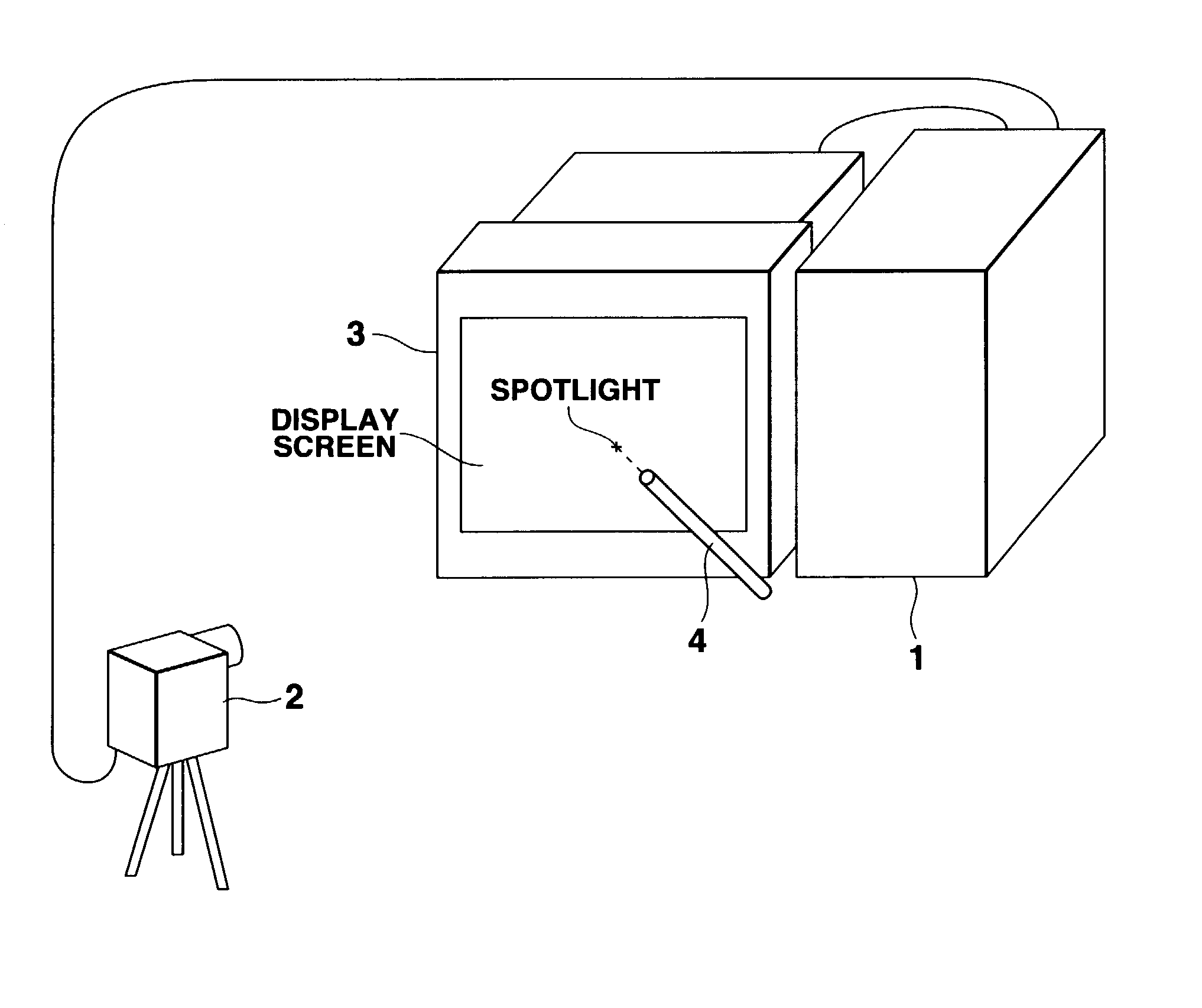
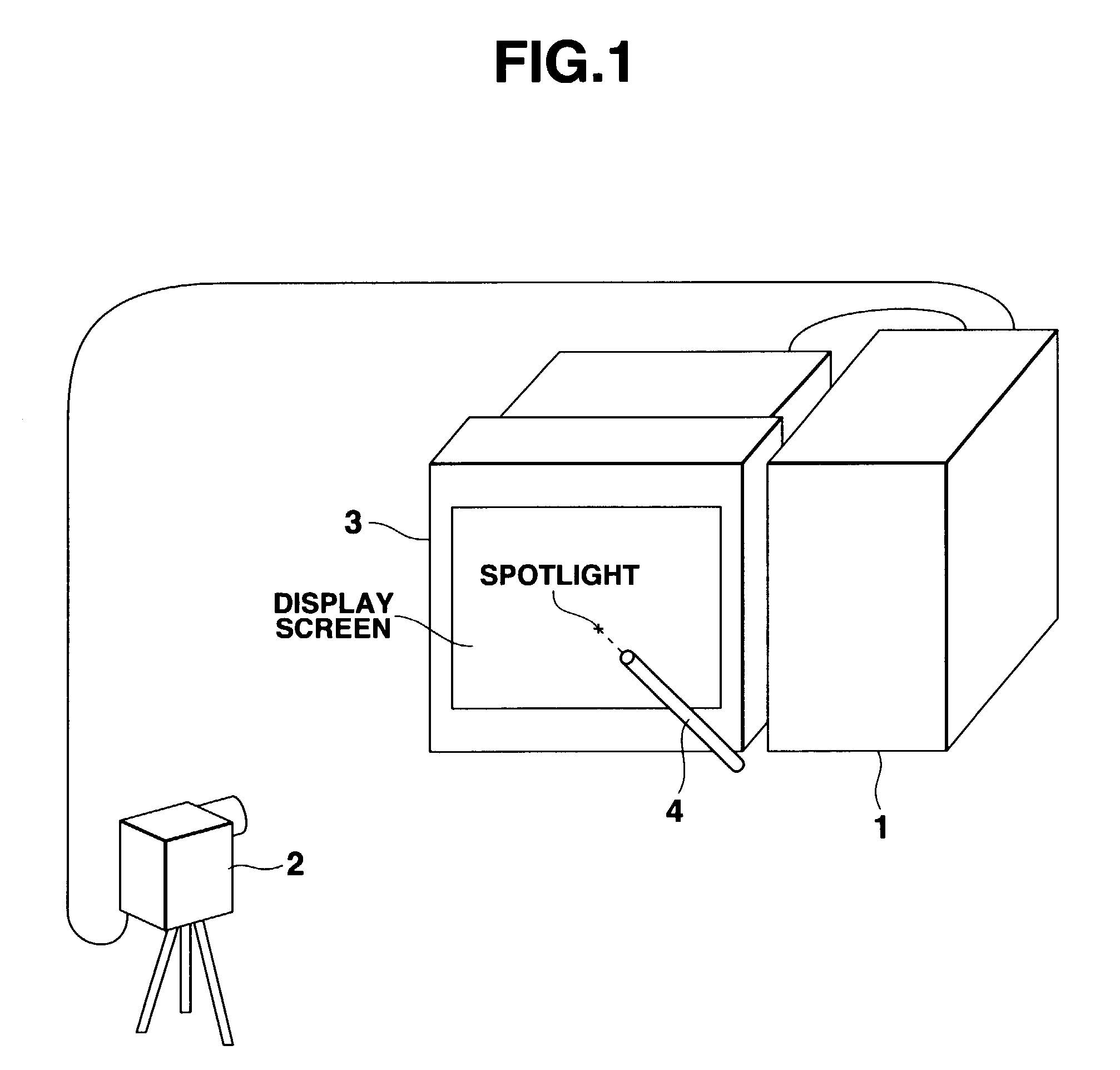
[0164]When this drawing system starts the drawing process, the image input unit 2 takes an image of the display screen of the display unit 3, generates image data representing the taken image, and supplies this image data to the central control unit 11 of the data processing device 1 (FIG. 3, step S1). Due to this step, the image of the display screen of the display unit 3 is input.

[0165]The image data generated by the image input unit 2 is composed of a plurality of pixel data each representing a position and pixel value of a pixel, where the display screen of the display unit 3 is regarded as a group of pixels arranged in a matri...

second embodiment

[0251]In the aforementioned step A11, this drawing system may automatically set the area, without the user's operation to point four points on the display screen of the display unit 3. The second embodiment of the present invention where area-setting is performed automatically will now be explained below.

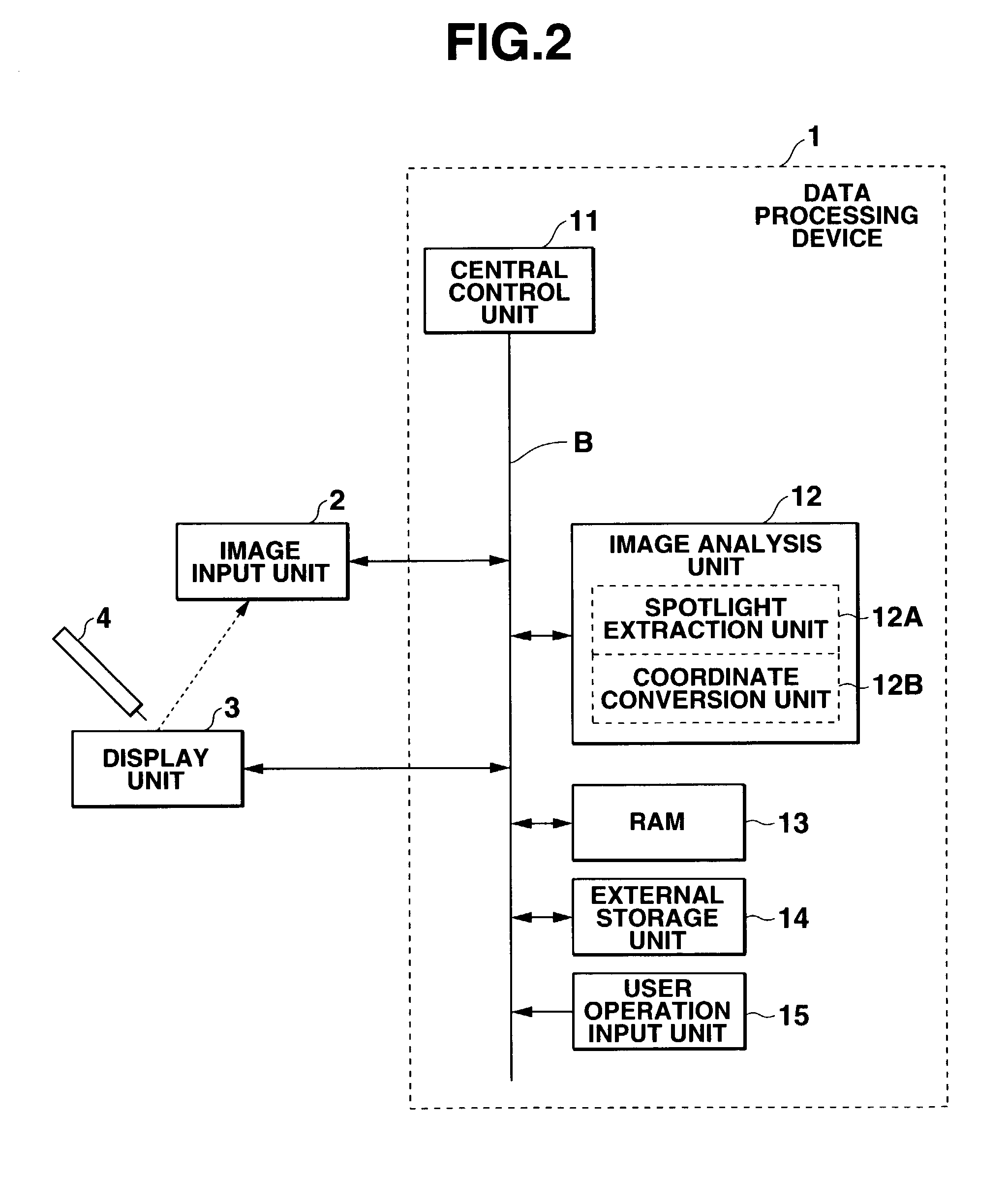
[0252]The physical structure of this drawing system is substantially the same as the structure shown in FIG. 2.

[0253]Functionally, the data processing device 1 of this drawing system obtains the positions of the points A, B, C, and D which are the vertexes of the quadrangle ABCD by performing a process shown in FIG. 17 as the process of step A11.

[0254]First, the central control unit 11 instructs the display unit 3 to display a rectangular frame representing the aforementioned rectangle A′B′C′D′ on the display screen (FIG. 17, step SB1). Then, the central control unit 11 declares usage of a two-dimensional variable array, and initializes this two-dimensional variable array by substit...

third embodiment

[0274]The spot displayed by the display unit 3 may have a predetermined brightness corresponding to the stage of brightness of the spotlight emitted from the light emitting unit 4. The drawing system according to the third embodiment of the present invention where the spot displayed by the display unit 3 has a predetermined brightness corresponding to the stage of brightness of the spotlight taken by the image input unit 2, will be explained below.

[0275]The physical structure of this drawing system is substantially the same as the structure shown in FIG. 2. However, the brightness of the spotlight emitted from the light emitting unit 4 is adjusted to any of N stages (N is an arbitrary integer equal to or greater than 2) in accordance with an operation of a user. (In the following explanation, a state where the spotlight is not emitted is regarded as having brightness of 0th stage when evaluated from the darkest stage. Further, to facilitate understanding, it is assumed that the colo...


PUM

PropertyMeasurementUnit
Distanceaaaaaaaaaa
Distanceaaaaaaaaaa
Coloraaaaaaaaaa

Abstract

A data processing apparatus includes a central control section, an image analysis section, a RAM (Random Access Memory), an external memory section and a user operation input section. The central control section is connected to the image analysis section, the RAM and the external memory section via a bus. Based on image data prepared by an image input section, the image analysis section performs a process of specifying where on the display screen of a display section a portion specified by the image input section lies.

Description

BACKGROUND OF THE INVENTION[0001]1. Field of the Invention[0002]The present invention relates to an image display device, an image display method, a program, and a projection system for drawing an image in accordance with an operation of an operator, on a display screen.[0003]2. Description of the Related Art[0004]When an image is projected on a screen and supplementary light is further projected on this screen, a technique for detecting the position of the supplementary light emitted from a laser pointer, etc. is used in order to make a change to the point which corresponds to the position of the image where the supplementary light is projected. Japanese Patent No. 2622620 discloses such a technique.[0005]However, according to the technique of Japanese Patent No. 2622620, when taking an image of the supplementary light (spot) projected on the screen in order to detect the position of the supplementary light, an image pickup device for taking an image must face its light receiving s...

Claims


Application Information

Patent Timeline
IPC IPC(8): G06K9/32G06F3/038G06F3/042
CPCG06F3/0426G06F3/0386
Inventor MATSUOKA, TAKESHIMATSUI, SHINICHIIIZUKA, NOBUOKASAHARA, TSUYOSHIMATSUDA, TAKASHINAKAGOMI, KOUICHI
Owner CASIO COMPUTER CO LTD
Why Eureka
Try Eureka