
Dual direction exercise treadmill with moment arm resistance
- Summary
- Abstract
- Description
- Claims
- Application Information
AI Technical Summary
Benefits of technology
Problems solved by technology
Method used
Image

Examples
second embodiment
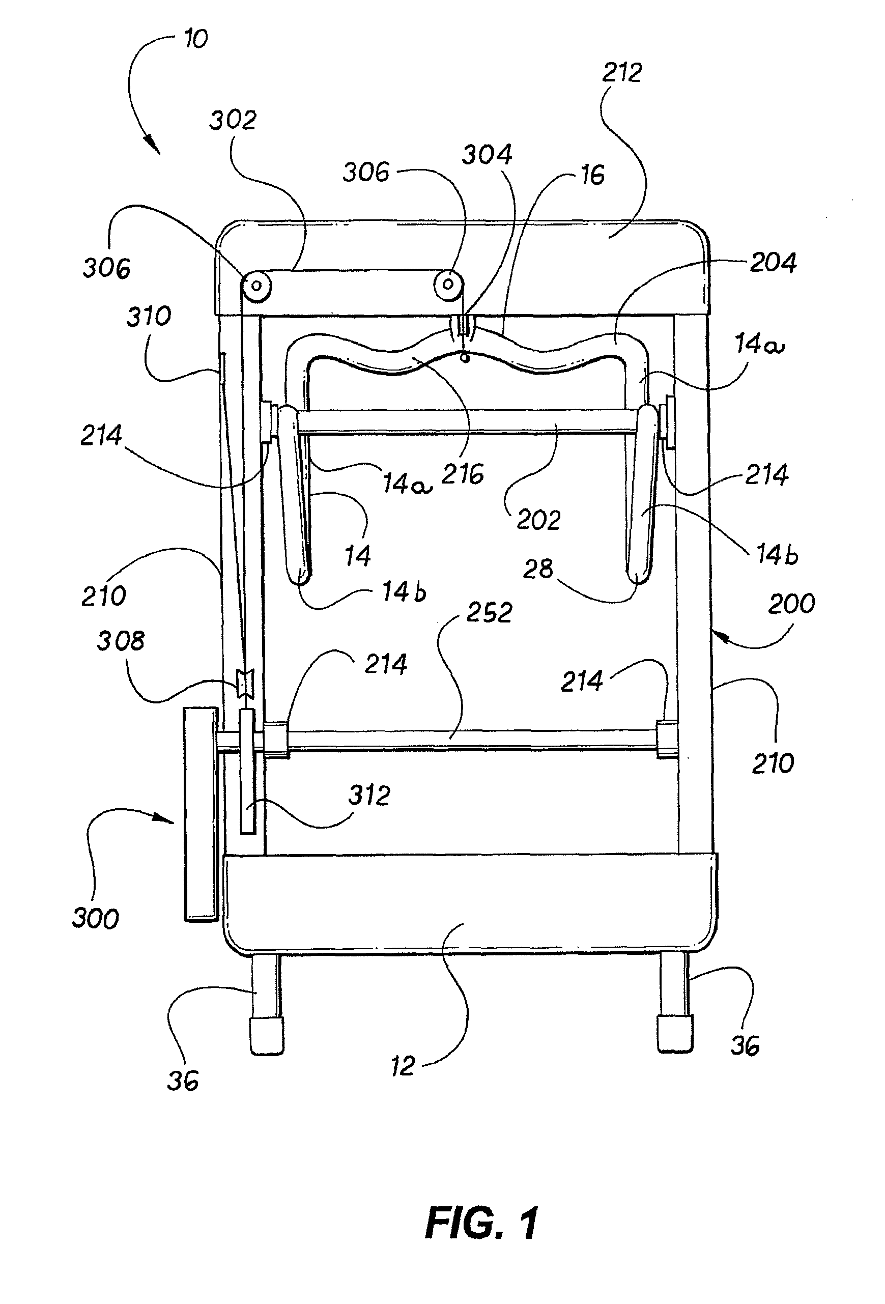
[0036]FIG. 5 is a side view of the moment arm weight resistance mechanism in the resting position. FIG. 6 is a side view of the moment arm weight resistance mechanism in a resistance position. FIG. 7 is a top view of an embodiment of the moment arm weight resistance mechanism of the invention. FIG. 8 is a side view of the embodiment of the moment arm weight resistance mechanism shown in FIG. 7. FIG. 9 is a side view of an alternate embodiment of the moment arm weight resistance mechanism of the invention. FIG. 10 is a sectional side view of the moment arm weight resistance mechanism shown in FIG. 3 in larger detail.
[0037]FIG. 11 is a sectional side view of a representative weight and weight adjusting drive that can be used with the present invention. FIG. 12 is a side view of the internal pulley and cable configuration between the resistance arm and the moment arm mechanism. FIG. 13 is a view of a representative control console and hand controller for the invention. FIG. 14 is a sid...
first embodiment
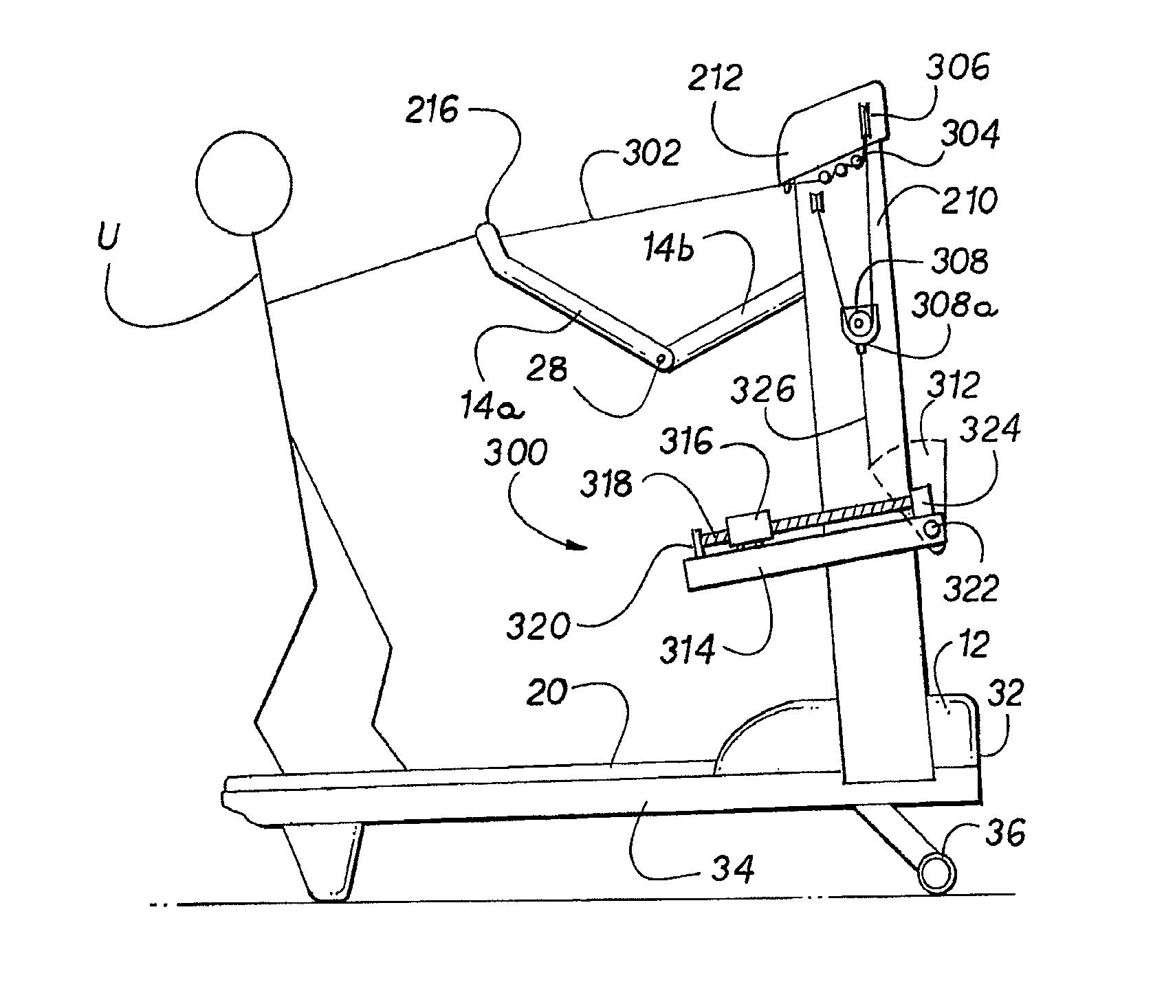
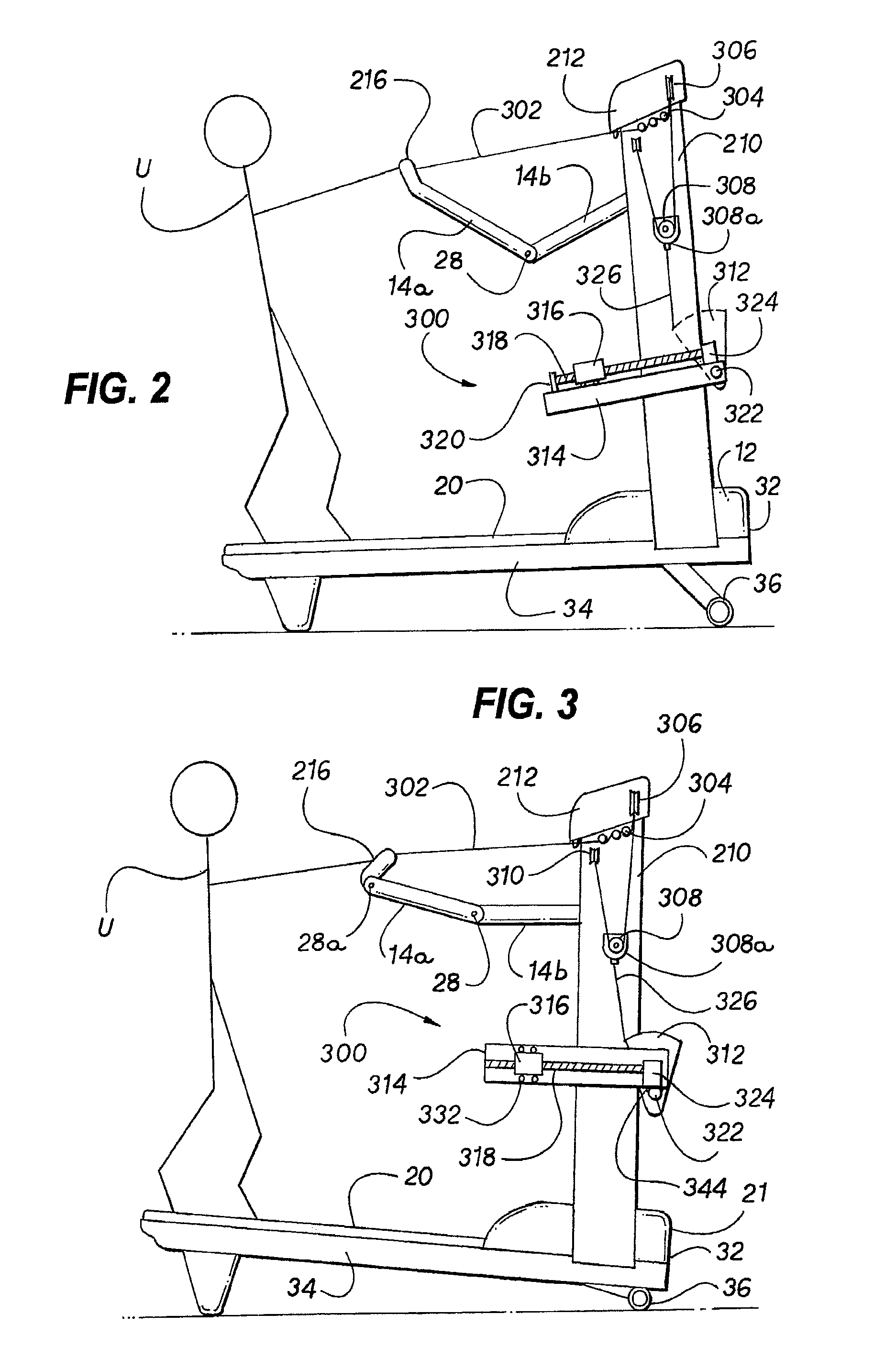
[0046]FIG. 2 is a side view of the treadmill 10 showing user U operating the treadmill 10 in a flat or level dragging or pulling simulation with a partial resistance arm 14 extension. In this position, user U is simulating a level surface dragging or pulling motion and is walking or running backwards and pulling on resistance arm 14, and thus pulling against moment arm weight resistance means 300. FIG. 2 shows the moment arm weight resistance mechanism 300 and a three-section resistance arm 14 in which the hand grip portion 216 is a part of the single upper resistance arm 14A. As can be seen, the multi-part structure of resistance arm 14 allows the appropriate motion of resistance arm 14 and hand controller 16 relative to user U for self-alignment of the resistance arm 14 and for proper and comfortable operation of treadmill 10. Moment arm weight resistance mechanism 300 is shown in an operating position, meaning moment arm weight resistance mechanism 300 is providing weight resista...
PUM
 Abstract
Description
Claims
Application Information