
Hose clamping device
A hose and clamping mechanism technology, applied in the field of hose clamps, can solve the problems of poor sealing safety performance, insufficient clamping force of high-pressure pipes, inconvenient loading and unloading, etc., achieving considerable economic benefits, saving manpower, material resources and financial resources, good performance
Patent Information
- Authority / Receiving Office
- CN · China
- Patent Type
- Patents(China)
- Current Assignee / Owner
- Publication Date
- 2010-12-22
Smart Images
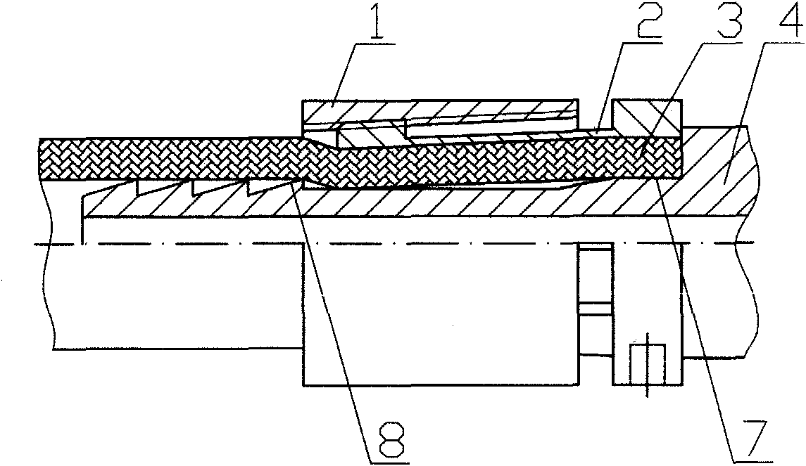
Figure 1 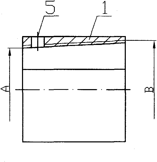
Figure 2 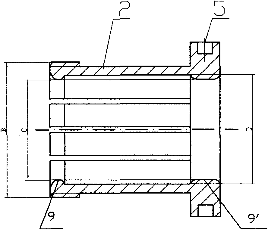
Figure 3
Abstract
Description
technical field
[0001] The invention relates to a hose clamp, in particular to a hose clamping device. Background technique
[0002] As we all know, regardless of vehicles, equipment or daily life, whether it is used to transport liquid or gas, whether it is used under normal pressure or under high pressure, the use of hose clamping devices abounds, with a large amount of use and a wide range of applications The vastness is self-evident. And the existing hose clamping device, the structure is simple and crude, such as the connection at the household gas pipeline interface is tightened with a metal wire, and the compressed gas output hoses such as the nozzles used for cleaning on the factory site or the anti-aircraft spray guns are clamped with U-shaped clamp screws. , to varying degrees, there are problems such as inconvenient loading and unloading, poor sealing safety performance, sharp corners and corners that are easy to scratch personnel or damage hoses; the structure i...
Examples
Embodiment 1
[0045] A hose clamping mechanism such as Figure 9 As shown, it includes a hose joint 4 coaxial with the hose 3, an inner cone nut 1 and a pipe bolt 2, the outer diameter of the hose joint 4 matches the inner diameter of the hose 3, and the inner cone nut 1, such as Figure 6 As shown, the large aperture end is the screw-in end, and the corresponding small aperture end is the end of the inner cone nut 1; the internal thread of the inner cone nut 1 is a tapered thread, and the small diameter of the thread at the end of the inner cone nut 1 A is slightly larger than the outer diameter of the hose; the pipe bolt 2, such as Figure 7 , Figure 8 As shown, the threaded end is evenly distributed along the circumferential direction of the pipe wall with more than two long strips parallel to the central axis, and the inner diameter C of the central hole is slightly larger than the outer diameter of the hose. When using this hose clamping device to clamp the hose, first insert the h...
Embodiment 2
[0054] Such as Figure 10 As shown, it is also an embodiment of the present invention. The difference from Embodiment 1 is that there are flanges 9 and 9' on the inner sides of the two ends of the pipe bolt 2 respectively, and the inner diameters of the flanges 9 and 9' are slightly It is larger than the outer diameter of the hose; the joint where the flange 9 away from the head of the pipe bolt 2 and the hose is arc-shaped, that is, the clamping position. This design is also to increase the clamping force, make the connection reliable, or be used in occasions with high working pressure.
[0055] The hose joint 4 of the present invention can be a joint of symmetrical shape that connects two or more directions, so as to realize the connection between two or more hoses. Such as Figure 11 As shown, the left and right symmetrical double hose joints 6 are used, and the rest of the structure is the same as that of the embodiment 2, which is used for clamping and connecting two ho...