
Turbine vane type of starting torque converter for hydraulic drive locomotive
A technology of hydraulic transmission and torque converter, applied in the field of hydraulic transmission locomotives, can solve the problems of low efficiency, inconspicuous blade streamline, uneven flow channel area, etc.
Patent Information
- Authority / Receiving Office
- CN · China
- Current Assignee / Owner
- Publication Date
- 2009-12-30
Smart Images
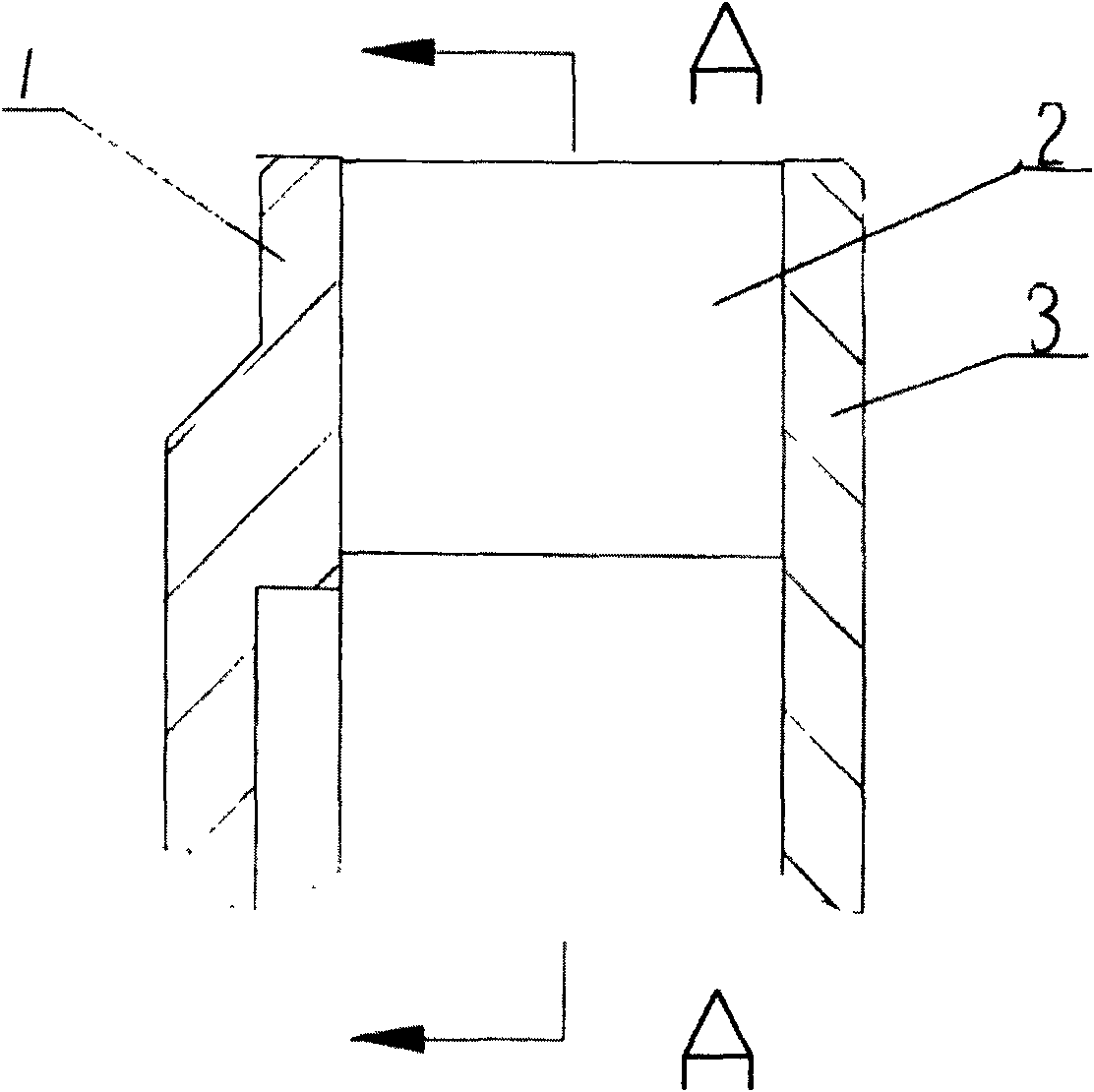
Figure 1 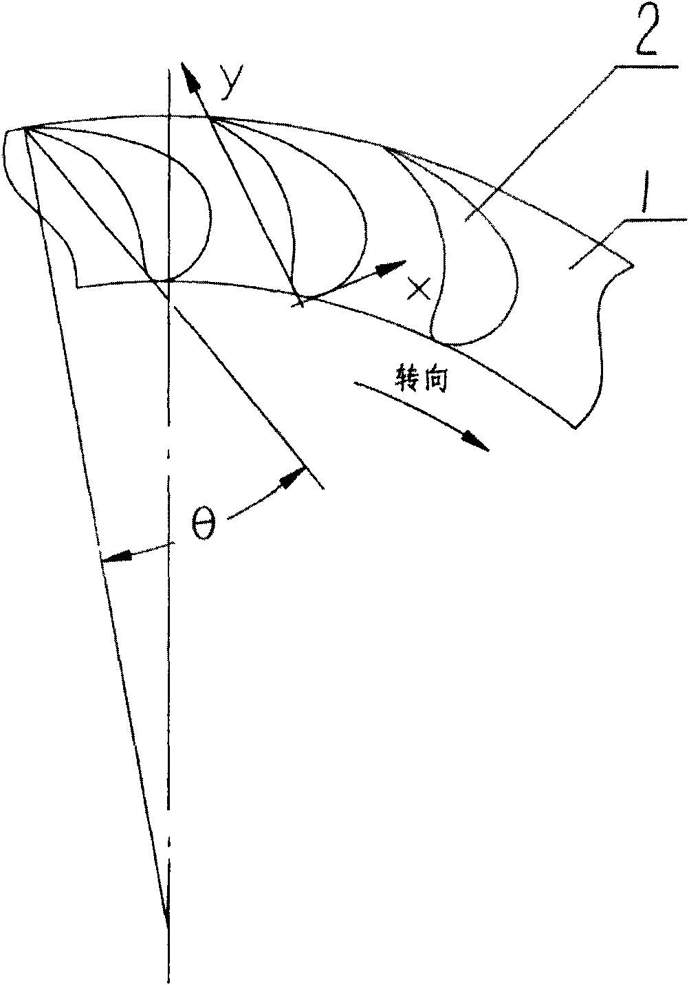
Figure 2 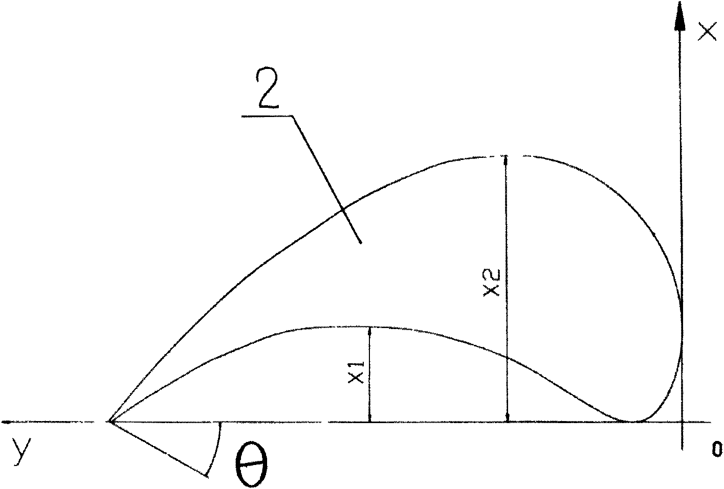
Figure 3
Abstract
Description
technical field
[0001] The invention relates to a hydraulic transmission locomotive, in particular to a hydraulic transmission device. Background technique
[0002] At present, hydraulic transmission technology is widely used in railway diesel locomotives and diesel multiple units because of its unique performance, high reliability, mature technology and high performance-price ratio. On a locomotive, one torque converter cannot meet the requirements of the continuous speed range of the entire traction characteristic of the locomotive, and two or more torque converters must be combined to form a hydraulic transmission device. According to the different working scope, it is divided into locomotive starting torque converter and locomotive running torque converter, which are referred to as starting torque converter and running torque converter respectively. What the present invention relates to is a starting torque converter, which works in the starting acceleration and low spe...
Examples
example 1
[0019] exist figure 1 , figure 2 and image 3 In the schematic diagram of the turbine blade profile of the starting torque converter for a hydraulic transmission locomotive shown, the turbine has two annular disks opposite and parallel to the turbine disks 1 and 2, and several blades are vertically fixed between the two annular disks. 3. They form cascades. These blades with the same structure and regularly arranged are all cylindrical shells with a leaf-like cross section. The front ends of these blades are all arranged on the inner diameter circle of the annular disk surface of the turbine disk, and the rear ends of these blades are all arranged on the outer diameter circle of the annular disk surface of the turbine disk. In the section of the above-mentioned blade, the two arc-shaped connecting lines from the front end to the rear end are different curves. The shape of the above-mentioned blades and the distance between the inner and outer sides can be expressed by a r...
example 2
[0025] Its structure is basically the same as Example 1, except that
[0026]
[0027]
[0028] Y value
[0029] Y value
[0030] The included angle θ between the line connecting the front end and the rear end of the blade of the present invention and the line connecting the center of the turbine disk and the rear end of the blade is 30°.