
Movable optical fiber connector with improved structure
An optical fiber connector and activity technology, applied in the field of optical connection devices, can solve the problems of unreliable fixation and difficult fixation of optical cables, and achieve the effects of speeding up docking, easy maintenance and replacement, and reliable fixation
Patent Information
- Authority / Receiving Office
- CN · China
- Patent Type
- Applications(China)
- Current Assignee / Owner
- Publication Date
- 2010-01-27
- Estimated Expiration
- Not applicable · inactive patent
Smart Images
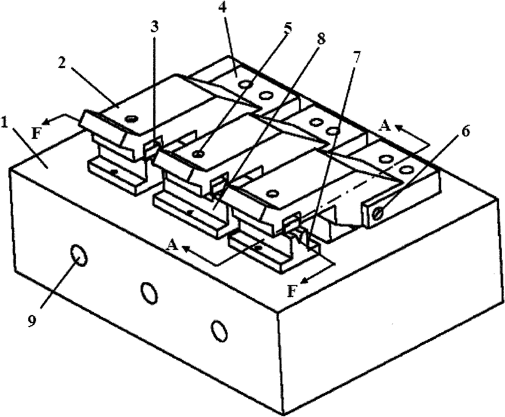
Figure 1 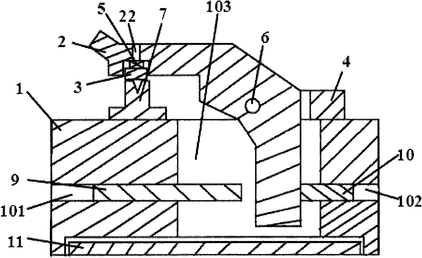
Figure 2 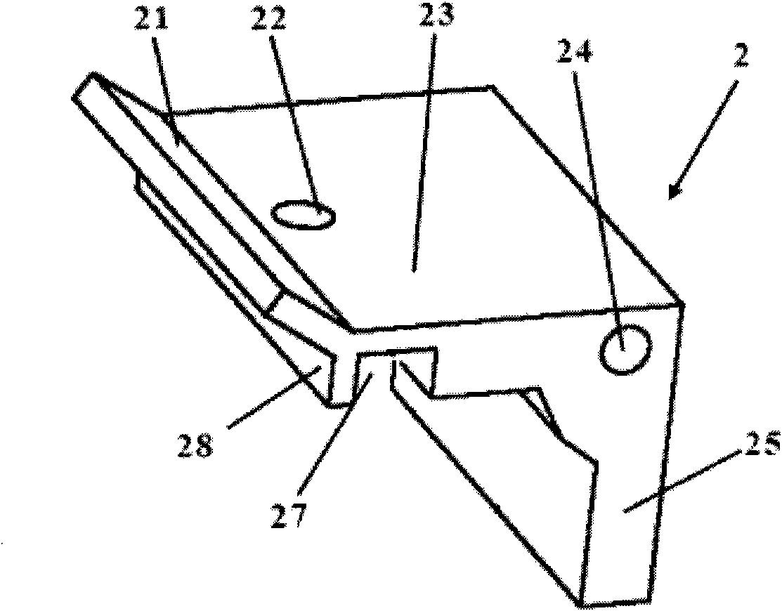
Figure 3
Abstract
Description
technical field
[0001] The invention relates to an optical connection device, in particular to an active optical fiber connector with improved structure. Background technique
[0002] With the development of high-speed broadband communication technology, the application of optical fiber transmission is becoming more and more extensive. Therefore, the demand for optical fibers and optical cables continues to rise. , it is necessary to test the optical performance of each optical fiber in the optical cable; the connection required in the test is a fast active connection. Chinese patent ZL200720146424.4 discloses an active optical fiber connector, which is very suitable for factory testing and other active connections. However, unfortunately, the V-shaped grooves on both sides of this fiber optic connector and the corresponding pressing blocks are placed horizontally, and the optical cable to be tested is often not easy to fix. When the optical cable slips slightly, the tested ...
Examples
Embodiment Construction
[0020]
[0021] Such as figure 1 and figure 2 As shown, the optical fiber connector with improved structure disclosed by the present invention includes: a base 1, the upper bottom surface of the base 1 near the front end is fixed with a V-shaped groove 7 on the left and a right and a V-shaped groove 8 in the middle, and the three V-shaped grooves 8 The groove is used to accommodate the reference optical fiber and the optical fiber to be tested; three concave plates 4 are fixed on the bottom surface of the base 1 near the rear end surface, the concave surface of the concave plate 4 faces the front end of the base 1, and the rear end of the pressure plate 2 is inserted In the recess of the board 4, three shafts 6 passing through the right side of the concave board 4 connect the three concave boards 4 with the three pressure plates 2 respectively. 2. The fiber tightness adjustment spring 5 located in the groove of the pressure plate 2 and the pressure block 3 located below t...