
Valve for fluid
A fluid and large fluid technology, applied in the field of metal rings, can solve problems such as damage, metal sheets 24 combined into one structure, and corrosion, and achieve the effect of improving service life
Patent Information
- Authority / Receiving Office
- CN · China
- Patent Type
- Applications(China)
- Current Assignee / Owner
- Publication Date
- 2010-06-09
- Estimated Expiration
- Not applicable · inactive patent
Smart Images
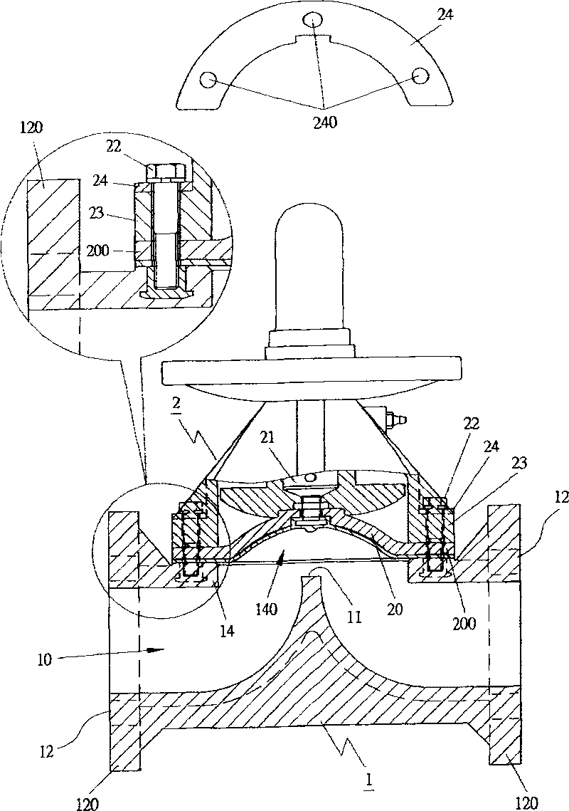
Figure 1 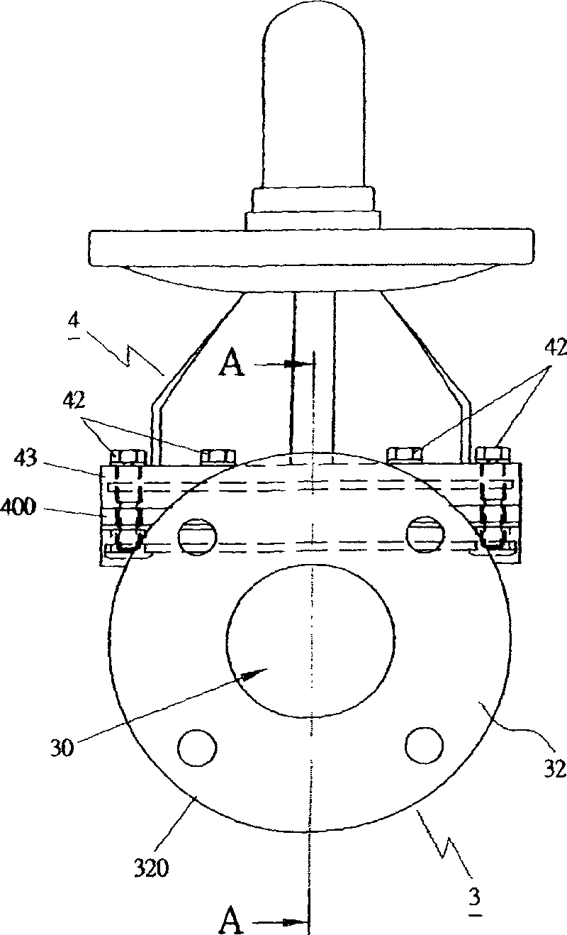
Figure 2 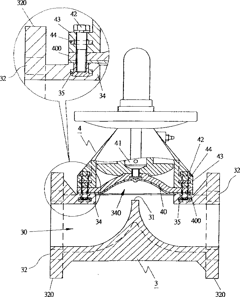
Figure 3
Abstract
Description
technical field
[0001] The present invention relates to a valve for fluid, especially a structural innovation of a valve for fluid that can be applied to various structures. The main purpose of the present invention is that one or more metal rings are integrally formed around the combined ring of the body ; and then one or more metal rings are integrally molded around the joint ring of the upper cover or joint, so that when the body is combined with the upper cover or joint, the fluid valve can withstand greater fluid pressure and improve the use of fluid. The service life of the valve can be widely used in various places of use. Background technique
[0002] According to commercially available valves for fluids, such as figure 1 As shown, the conventional structure is explained by a diaphragm valve, which includes: a body 1, an integrally formed fluid flow hole 10 is provided inside the body 1, and a flange 11 is located in the center of the fluid flow hole 10, and the Th...
Examples
Embodiment Construction
[0030] The fluid valve or valve of the present invention refers to a fluid valve or valve that can be applied to various structures, such as a diaphragm valve; or a diaphragm valve of any type; or a swing diaphragm valve; or a check valve; or a butterfly valve, for To enable your examiner to fully understand the present invention, it is explained as follows according to the attached drawings:
[0031] Such as figure 2 and 3 , Image 6 The embodiments shown are all diaphragm valves; as Figure 7 and 8 The embodiment is by any type (TRUE UNION) diaphragm valve; Figure 9 The embodiment shown is a swing diaphragm valve; as Figure 10 The embodiment shown is a check valve; as Figure 11 and 12 The illustrated embodiment is a butterfly valve, and each of the above embodiments includes:
[0032] The body 3 is provided with an integrally formed fluid flow hole 30 on the body 3, and the flow hole 30 is connected with the image 3 ;or Image 6 ;or Figure 7 ;or Figure 9 T...