
Brake mechanism for coil spring-type operation device
A technology of operating device and braking mechanism, which is applied to the power device inside the switch, etc., can solve the problems of poor reliability of the mechanism, difficult spring opening, closing function, large volume, etc., and achieve simplified structure, good reliability and stability Effect
Patent Information
- Authority / Receiving Office
- CN · China
- Current Assignee / Owner
- Publication Date
- 2010-07-14
- Estimated Expiration
- Not applicable · inactive patent
Smart Images
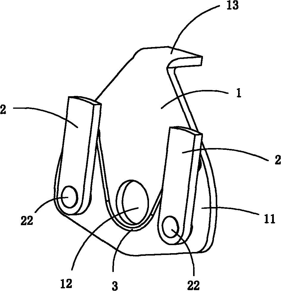
Figure 1 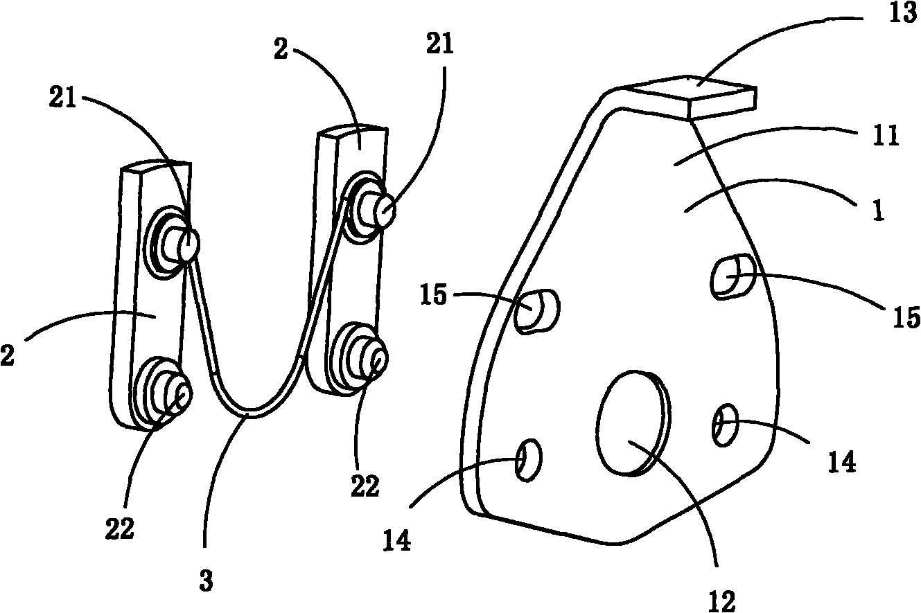
Figure 2 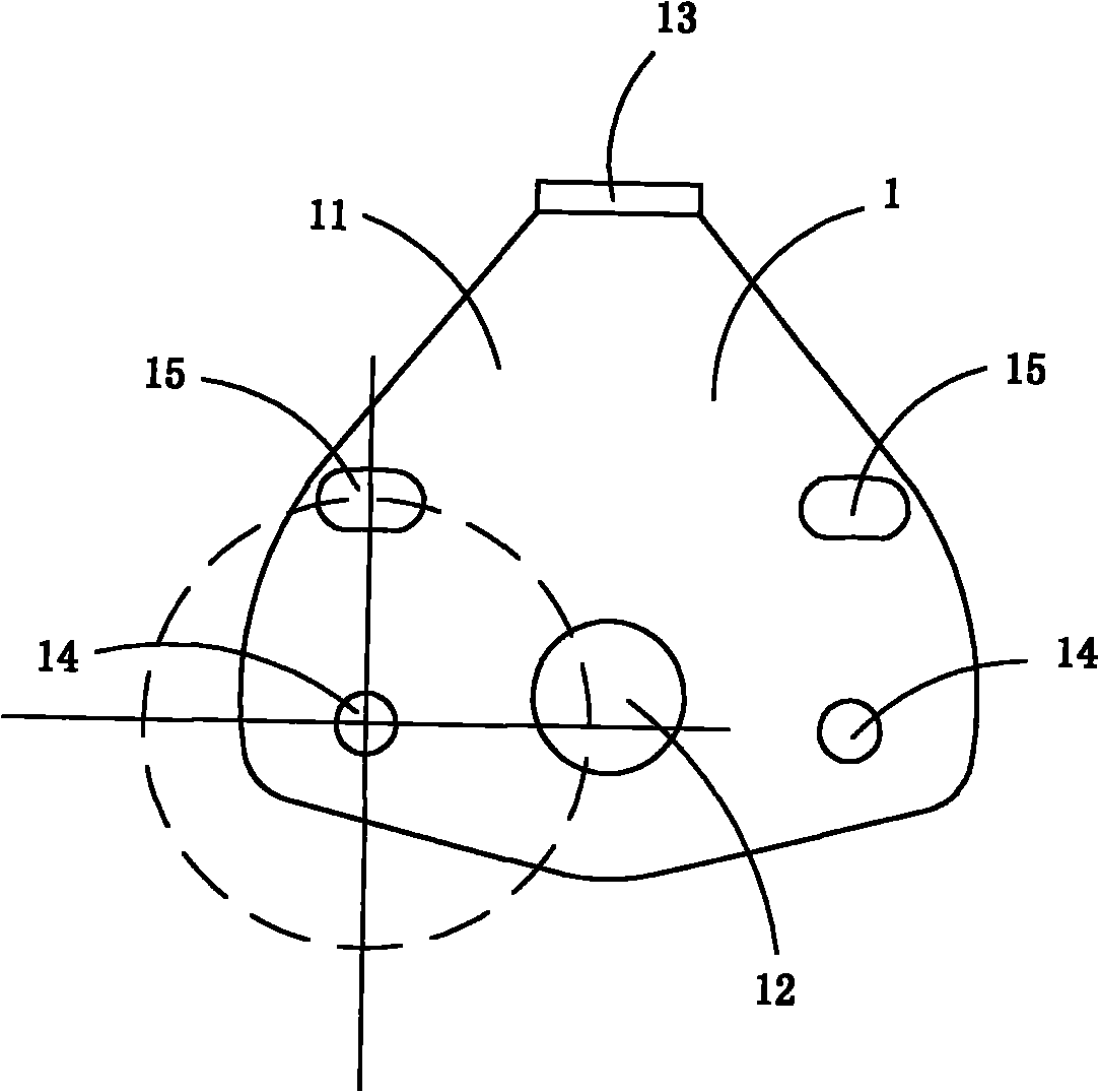
Figure 3
Abstract
Description
technical field
[0001] The invention belongs to the technical field of structural design of high-voltage electrical appliances, and in particular relates to a braking mechanism used in a scroll spring operating device. Background technique
[0002] The spring operating device of the traditional load switch generally adopts a helical tension spring or a compression spring. However, adopting the coil spring as the energy storage device inevitably has the following defects: first, the volume is too large. Second, it is difficult to achieve two-way energy storage, so it is difficult to use a spring to complete the opening and closing functions. Third, the structure is complicated, the number of components is too large, and the reliability of the mechanism is poor.
[0003] Patent document CN2423648Y discloses a planar scroll spring energy storage and release mechanism. The whole device is composed of a first chamber and a second chamber composed of three curved plates. There a...
Examples
Embodiment 1
[0015] Figure 1 to Figure 3 A specific embodiment of the invention is shown in which figure 1 It is a schematic diagram of a three-dimensional structure of the present invention; figure 2 for figure 1 An exploded view of the brake mechanism shown; image 3 for figure 1 A front view of the output plate in the brake mechanism shown.
[0016] This embodiment is a brake mechanism used in a scroll spring type operating device, including an output plate 1, two brake detents 2 and a support spring 3 for providing return elastic force for the detents 2;
[0017] It is characterized in that: the output plate 1 includes a plate-shaped body 11, and the body 11 is provided with a shaft hole 12, a baffle plate 13, two installation holes 14 for installing the detent 2 and two for limiting Limiting holes 15 for the rotation angle of the detent 2; each limiting hole 15 is arranged directly above a corresponding mounting hole 14;
[0018] The two detents 2 are symmetrically arranged on...