
Crawler crane with lateral reinforcement structure
A technology of crawler crane and strengthening structure, which is applied to cranes, ships, cargo handling equipment and other directions, can solve the problems of complex design, high processing cost, high material consumption, etc., and achieves low manufacturing cost, convenient transportation and less material consumption. Effect
Patent Information
- Authority / Receiving Office
- CN · China
- Patent Type
- Applications(China)
- Current Assignee / Owner
- Publication Date
- 2010-08-25
- Estimated Expiration
- Not applicable · inactive patent
Smart Images
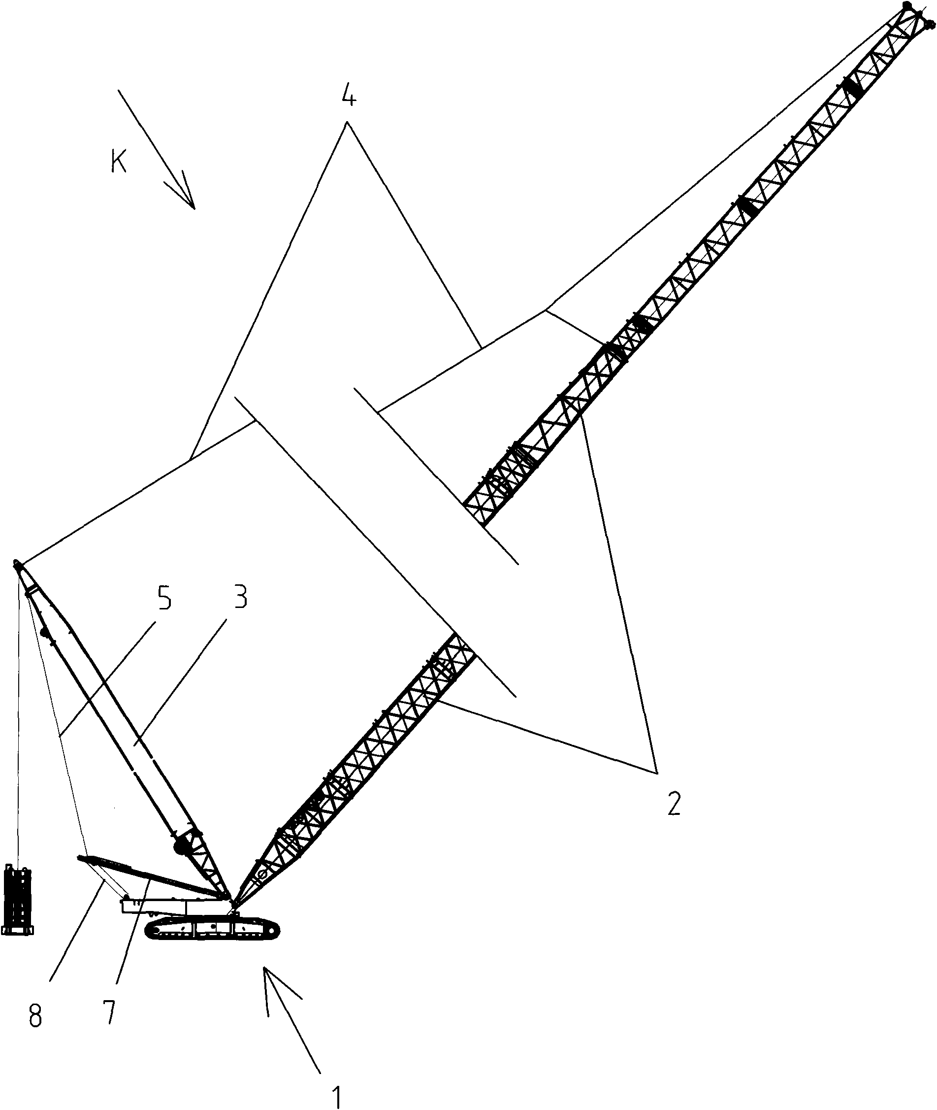
Figure 1 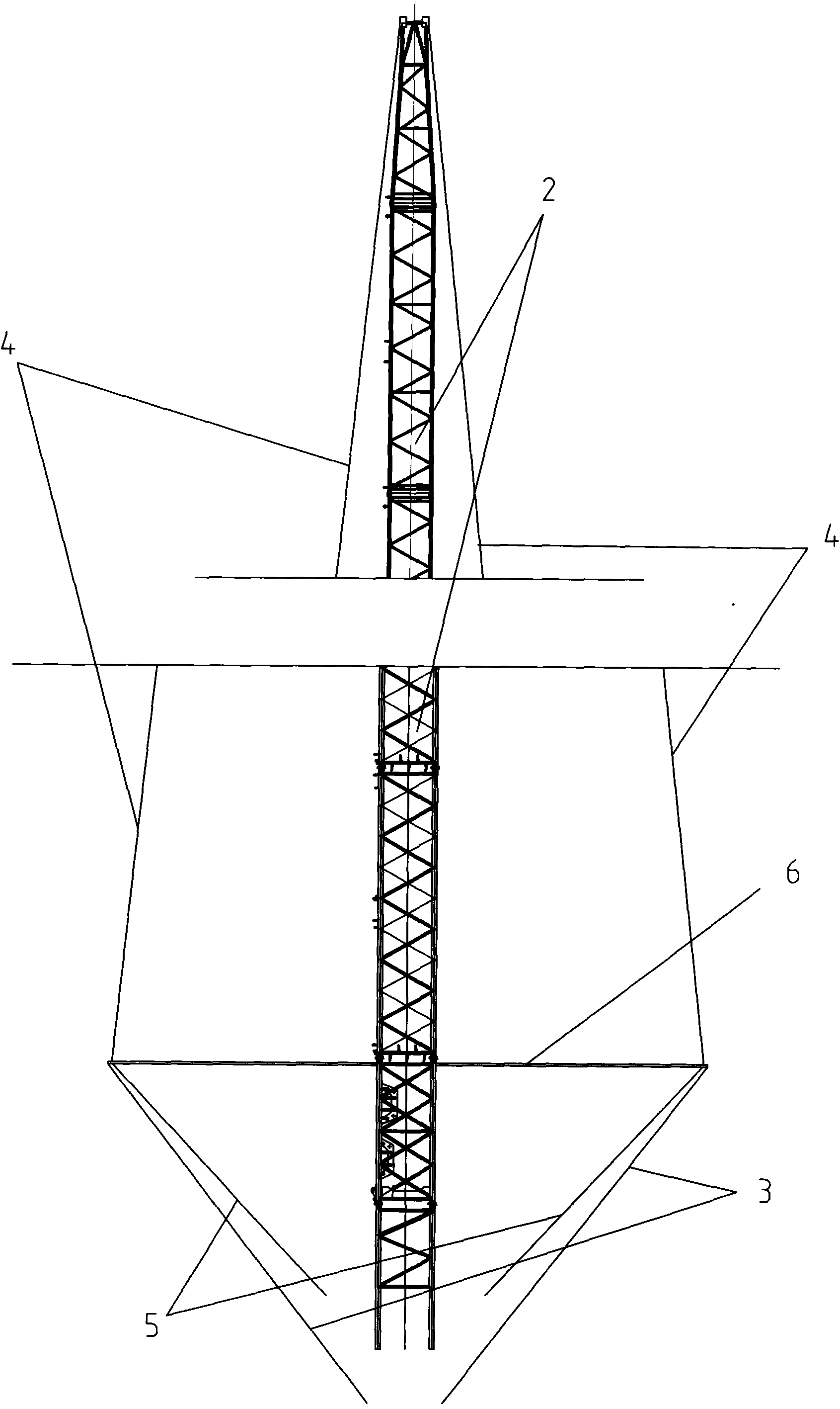
Figure 2 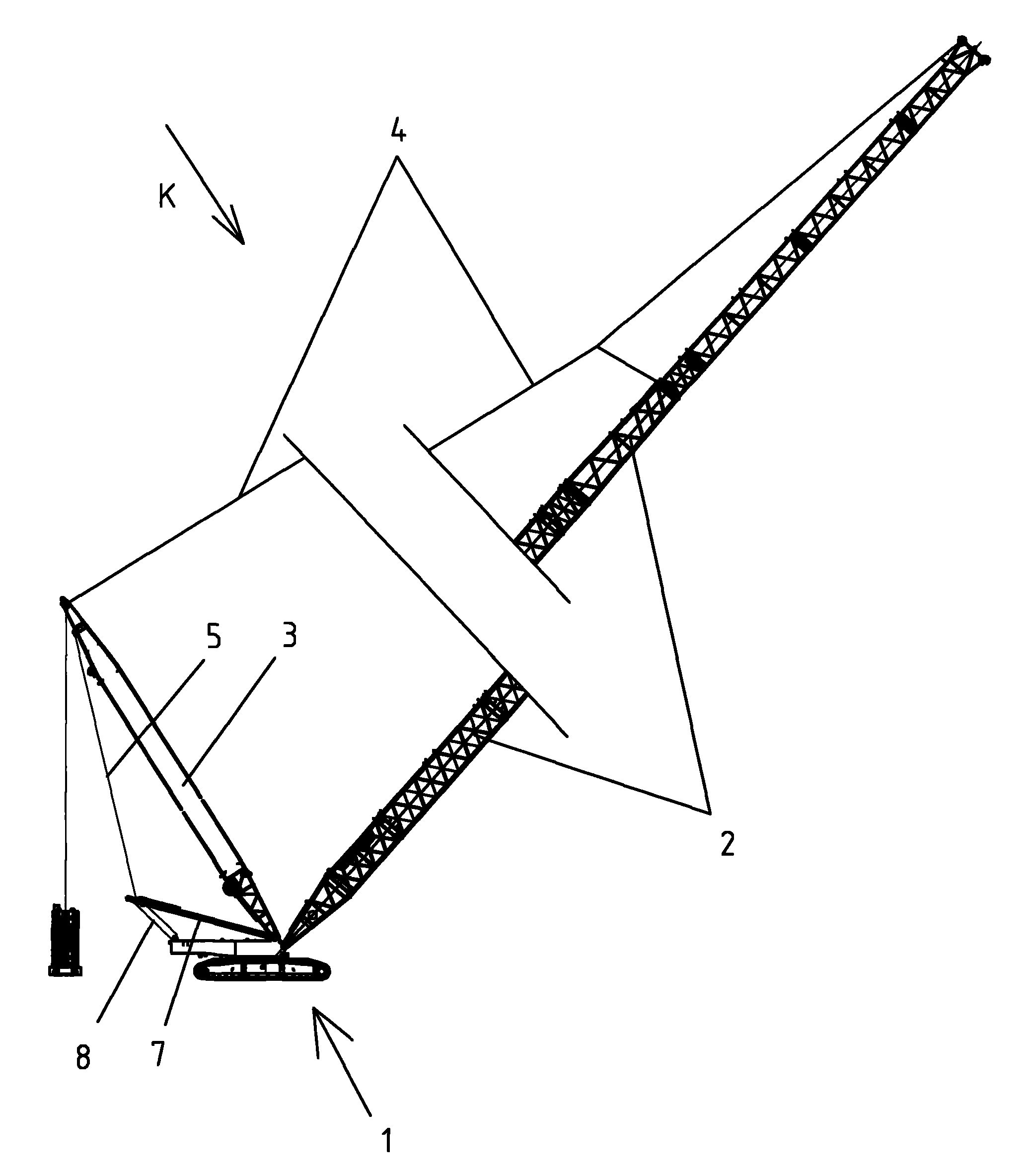
Figure 3
Abstract
Description
technical field
[0001] The invention relates to a crane, in particular to a crawler crane with a lateral reinforcement structure. Background technique
[0002] At present, the lifting capacity of crawler cranes has exceeded 1,000 tons, and the length of the jib is more than 100 meters. The pin shaft is connected with a front stay cable, the back stay cable is connected between the superlift mast top and the mast top through the pin shaft, and the main luffing rope is connected between the mast top and the crane body. The above-mentioned super-lifting mast, mast, front stay cable, and back stay cable are a group and are located on the symmetrical center plane of the crane body and the jib. The crawler crane with this structure has poor lateral stability during work. In order to enhance the lateral stability, some booms are designed as a double-parallel or "H"-shaped structure, and some are designed as a double-intersecting or "A"-shaped structure. Because two sets of booms ...
Examples
Embodiment Construction
[0010] Such as figure 1 , 2 Shown: 1 is the crane body, the crane body 1 is connected with the bottom rotating shaft of the jib 2, the super-lifting mast 3, and the mast 7, and the front end is connected by a pin shaft between the top of the jib 2 and the top of the super-lifting mast 3. The stay cable 4 is connected with the back stay cable 5 through the pin shaft between the top of the superlift mast 3 and the top of the mast 7, and the main luffing rope 8 is connected between the top of the mast 7 and the crane body 1. The above-mentioned superlift mast 3, mast 7, front stay cable 4, and back stay cable 5 are two groups, and are symmetrically arranged left and right with respect to the central plane of the crane body 1 and the jib 2. The bottom ends of the two super-lifting masts 3 are located at the center of rotation of the crane body 1 and the root of the jib 2, and the upper parts of the super-lifting masts 3 are respectively inclined to both sides to form a symmetrica...