
Continuous punching and nut riveting device for automobile door lock catch
A technology of automobile door locks and nuts, which is applied in the field of automobile manufacturing, can solve problems such as splashing, high labor intensity, smoke and dust, human health and environmental hazards, and achieve accurate positioning of material belts, reduce labor intensity of workers, stable quality and environmental protection Effect
Patent Information
- Authority / Receiving Office
- CN · China
- Patent Type
- Patents(China)
- Current Assignee / Owner
- Publication Date
- 2013-09-04
- Estimated Expiration
- Not applicable · inactive patent
Smart Images
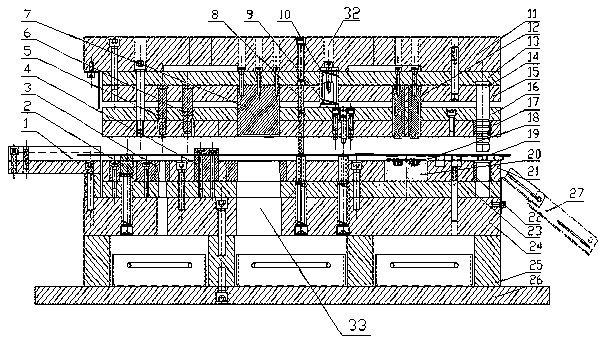
Figure 1 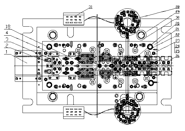
Figure 2 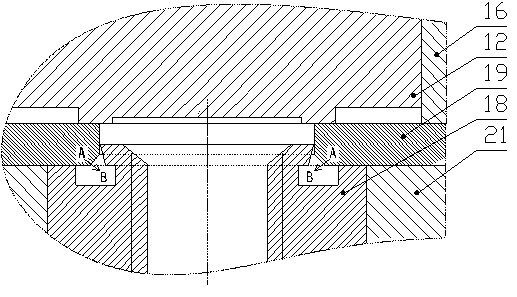
Figure 3
Abstract
Description
technical field
[0001] The invention relates to the technical field of automobile manufacturing, and is a device for continuously punching riveting nuts on a material belt when making door lock buckles. Background technique
[0002] Image 6 Shown is a three-dimensional schematic diagram of the universal door lock catch of an automobile. The door lock catch is an assembly of a strike plate with a serial number of 34 and a nut shown in a serial number of 35, and is installed in the inner frame of the automobile door to fix the door lock. Automobile door locks are supplied to many models, with the same or similar structure and four pieces for one car with four doors. The market demand is huge. At present, the production of locks usually adopts the process scheme of stamping (blanking punching, forming, punching chamfering) + welding, which has the following shortcomings:
[0003] 1. The structure of the stamping die is simple, but three sets of dies are required for blanking ...
Examples
Embodiment Construction
[0021] like figure 1 , figure 2 , Figure 5 As shown, the lower supporting plate 26 is installed on the workbench of the press, and the lower die base 24 is connected with the feet 25 and the lower supporting plate 26 with bolts and positioned with pins to fix the punching die 3 and the riveting die of the lower die assembly. 20. The die fixing frame 21 of the floating block 2, the material guide block 4, and the inner guide sleeve 22 is connected to the lower mold base 24 through the lower backing plate 22 with bolts and positioned with pins, and the floating block 2 lifts the material belt 19 The material guide block 4 plays the role of guiding the material belt 19, the inner guide sleeve 22 and the inner guide post 14 cooperate to guide the gap between the punch and the die, the riveting die 20 is embedded in the die fixing plate 21, and the guide Material rack 1 is contained on the lower mold base 24 and connects the circular pin positioning with bolts, and the lower m...