
Gas cooled type communication cabinet
A communication cabinet, air-cooled technology, applied in the direction of cooling/ventilation/heating transformation, electrical equipment shell/cabinet/drawer, electrical components, etc., to avoid interference, avoid influence, and improve the efficiency of air conditioning
Patent Information
- Authority / Receiving Office
- CN · China
- Patent Type
- Applications(China)
- Current Assignee / Owner
- Publication Date
- 2011-11-09
Smart Images
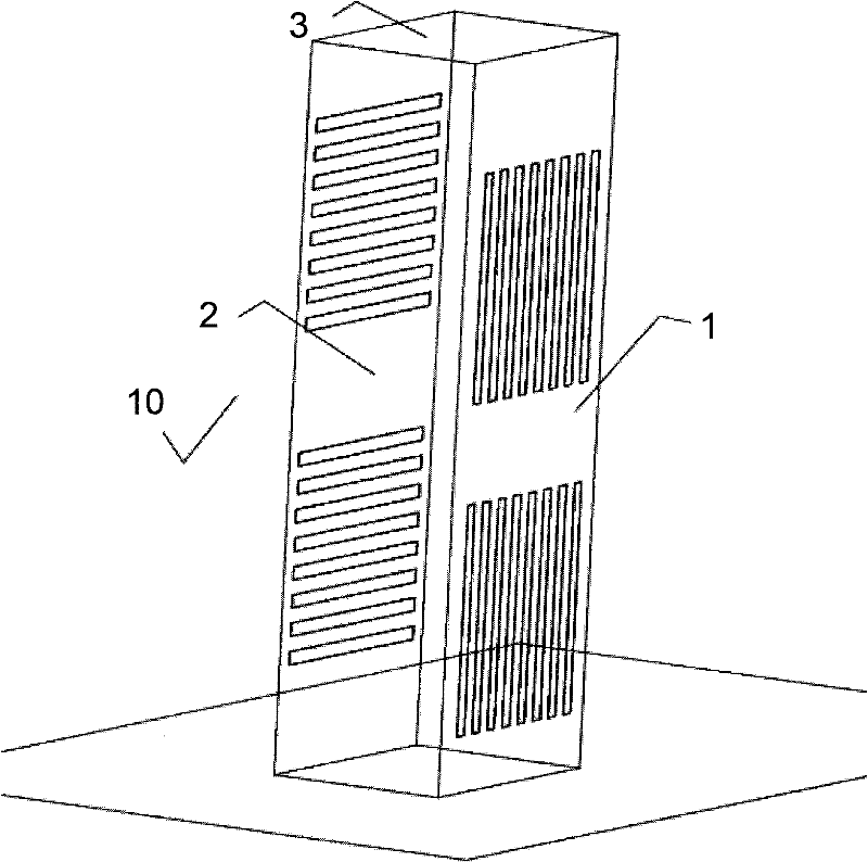
Figure 1 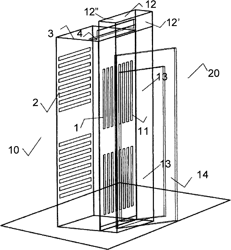
Figure 2 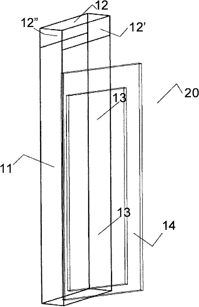
Figure 3
Abstract
Description
technical field
[0001] The invention relates to a communication cabinet, especially an air-cooled communication cabinet. Background technique
[0002] With the development of communication and electronic integrated monitoring technology, servers and data centers are widely used, and the cabinet has undoubtedly become the basic unit and carrier of these data centers and servers. There are usually multiple cabinets in an independent closed room in the data center, and a large number of electrical equipment and components are installed in each cabinet, such as common printed circuit boards, which are arranged in a compact and orderly manner and input current to realize the corresponding function. The data shows that the input current per cabinet is about 10A, and a considerable part of this current will be converted into heat and dissipated. The released heat will react to the surrounding electrical components and affect its normal operation. Therefore, it is necessary to dis...
Examples
Embodiment Construction
[0017] The present creation discloses an air-cooled communication cabinet, figure 1 The three-dimensional schematic diagram of the cabinet 10 in the present invention is shown. The common cabinet is a rectangular parallelepiped with a certain height, which includes: the inlet end face 1 for entering the cooling gas and the exhaust end face 2 for discharging the heating gas, and the top 3 of the cabinet. Usually the cabinet basically provides protection and support for a pair of internal equipment in a closed structure.
[0018] figure 2 It is a three-dimensional schematic diagram of the cabinet in which the device is installed in the present invention. This figure is an example of the device 20 installed on the inlet end face 1 where the cooling gas enters. It should be pointed out that the exhaust end face 2 installed on the cabinet 10 to discharge the heating gas also has a similar structure and function. It can be seen from this figure that the air-cooled communication c...