
Laser cutting head displacement sensor with multi-point measurement function
A technology of laser cutting head and displacement sensor is applied in the field of laser cutting head displacement sensor with multi-point measurement function to achieve the effects of improving detection accuracy, easy attitude and easy adjustment
Patent Information
- Authority / Receiving Office
- CN · China
- Patent Type
- Applications(China)
- Current Assignee / Owner
- Publication Date
- 2012-05-02
- Estimated Expiration
- Not applicable · inactive patent
Smart Images
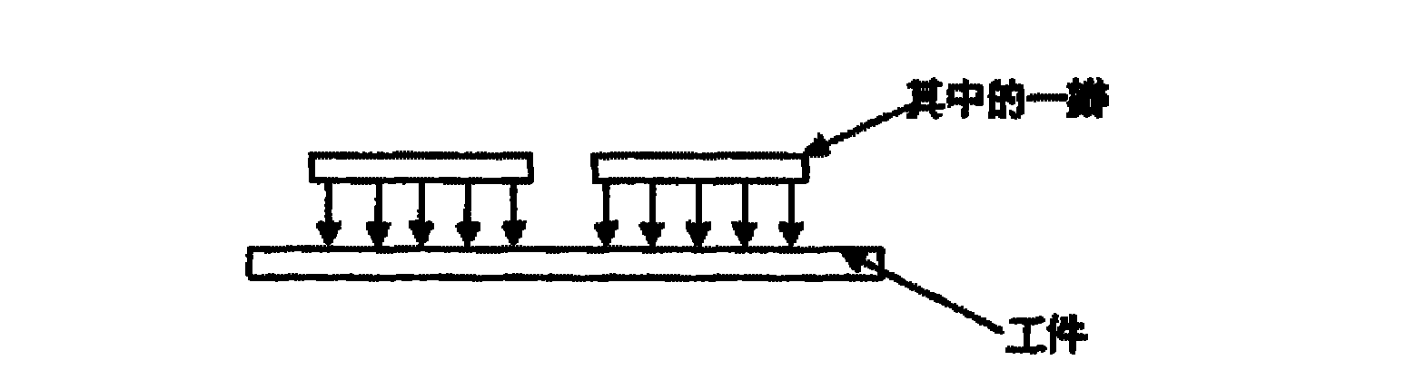
Figure 1 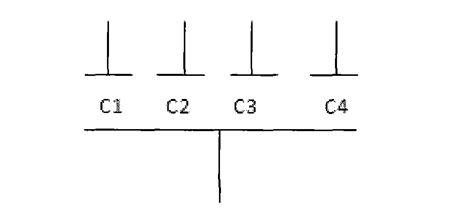
Figure 2 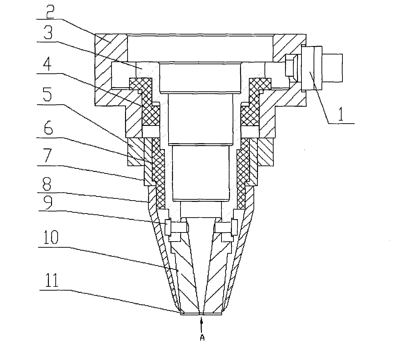
Figure 3
Abstract
Description
technical field
[0001] The invention belongs to the technical field of laser focus position detection and surface method vector detection of processed materials in laser three-dimensional cutting, and in particular relates to a measurement method with multi-point measurement function and a laser cutting head displacement sensor with multi-point measurement function, which can quickly Automatic vertical positioning of the laser head and detection of the distance between the laser head and the workpiece. Background technique
[0002] In the laser cutting process, in order to ensure the cutting quality, it is necessary to maximize the power density at the incision, which requires a certain gap between the nozzle of the cutting head and the surface to be processed, and the gap must be constant. The relative position between the laser beam focus point and the workpiece, that is, the defocus amount, is an important process parameter of laser cutting. During the cutting process, it...
Examples
Embodiment Construction
[0022] The structure of the laser cutting head displacement sensor of the present invention mainly includes: a sensing line connector 1, a connecting seat 2, a split metal connecting sleeve 3, a fixed insulating sleeve 4, a fixed shielding cover 7, a movable shielding cover 8, a laser cutting head The nozzle 10 etc., wherein the split nozzle 10 and the induction plate 11 are the main design parts of the present invention. The connecting seat 2 is used to connect with the components on the sensor, the sensor line connector 1 is arranged on the side of the connecting seat 2, and is used to transmit the signal of the sensor to the control system, and the split metal connecting sleeve 3 is inside the connecting seat 2, and the The effect of the wire, because if the lead wire is used, it may cause the lead wire to move and rotate. In order to insulate the connecting sleeve 3 from other parts, a fixed insulating sleeve 4 is provided between the connecting sleeve 3 and the connecting...