
Rewinding straightening device for tire bead steel wires
A bead wire and straightening technology, which is applied in the field of bead wire rewinding and straightening devices, can solve problems such as broken wires, disordered use by customers, and affecting the straightness of steel wires, so as to meet the straightness requirements and eliminate residual Stress, the effect of reducing scrap
Patent Information
- Authority / Receiving Office
- CN · China
- Patent Type
- Applications(China)
- Current Assignee / Owner
- Publication Date
- 2012-07-04
Smart Images
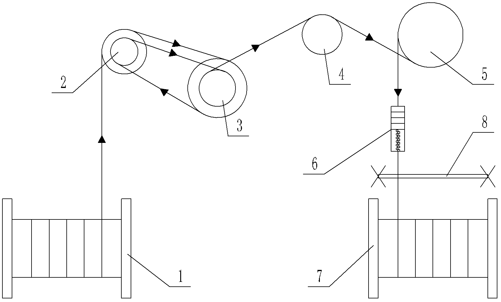
Figure 1 
Figure 2 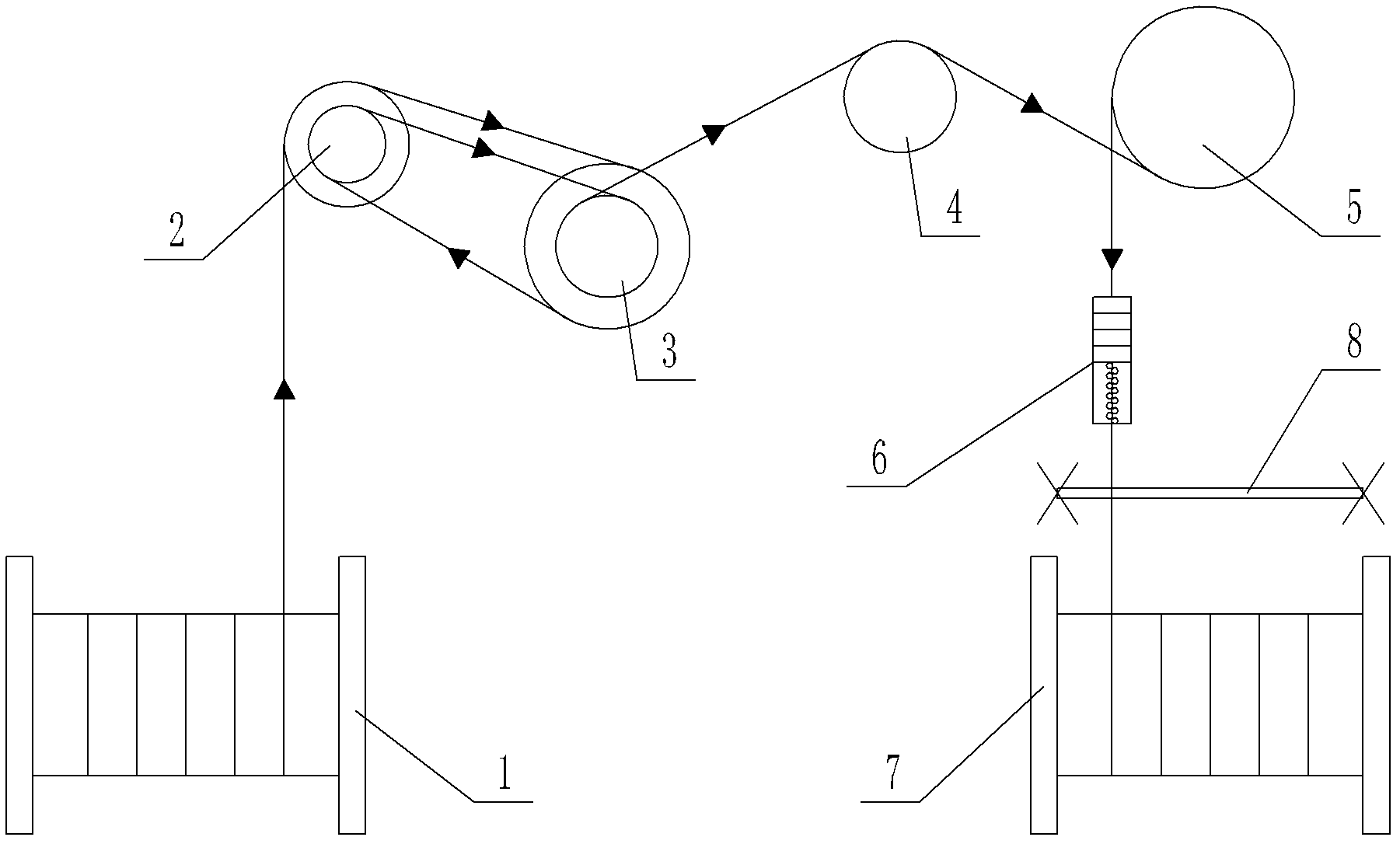
Figure 3
Abstract
Description
technical field
[0001] The invention relates to a bead steel wire rewinding and straightening device. Background technique
[0002] In the traditional production process of bead wire, since the deformation of the steel wire in the mold is uneven, the uneven deformation will generate residual stress, which can generally be eliminated by tempering and roller straighteners, but sometimes The residual stress cannot be eliminated due to poor straightener or improper adjustment of the straightener, which will affect the straightness of the steel wire. In serious cases, the entire steel wire will be unusable and scrapped; in addition, during the tempering production of the bead wire, There will be poor cable quality due to equipment or human factors, which will cause customers to mess up when using it or cause disconnection due to line pressure. Contents of the invention
[0003] The object of the present invention is to provide a bead wire rewinding and straightening device for...
Examples
Embodiment Construction
[0014] The present invention will be described in detail below in conjunction with the embodiments shown in the accompanying drawings.
[0015] as attached figure 1 As shown, the bead wire rewinding and straightening device of the present invention includes a pay-off shaft 1, a take-up shaft 7 and a rewinding and straightening mechanism. The wire passing wheel 3, the second wire passing wheel 4 that is rotated, the traction wheel 5 that is rotated, and the straightener 6, the steel wire released from the pay-off shaft 1 is wound on the tension induction wheel 2 and the first wire passing wheel 3 , the steel wire wound out from the first wire passing wheel 3 passes through the second wire passing wheel 4 and then winds on the traction wheel 5, and the steel wire wound out from the traction wheel 5 passes through the straightener 6 and is wound on the take-up shaft 7 , the take-up shaft 7 is driven by a motor, and an induction device is installed on the tension induction wheel ...