
Integral large flow check valve
A large flow, one-way valve technology, applied in fluid pressure actuation devices, fluid pressure actuation system components, mechanical equipment, etc., can solve problems such as large flow fluctuations in coolers, cooler bursts, and large flow pressure drops , to achieve the effect of novel and practical structure, preventing large flow and small flow pressure drop
Patent Information
- Authority / Receiving Office
- CN · China
- Patent Type
- Patents(China)
- Current Assignee / Owner
- Publication Date
- 2016-03-16
Smart Images
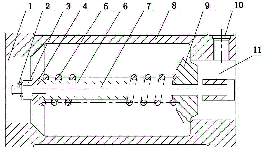
Figure 1 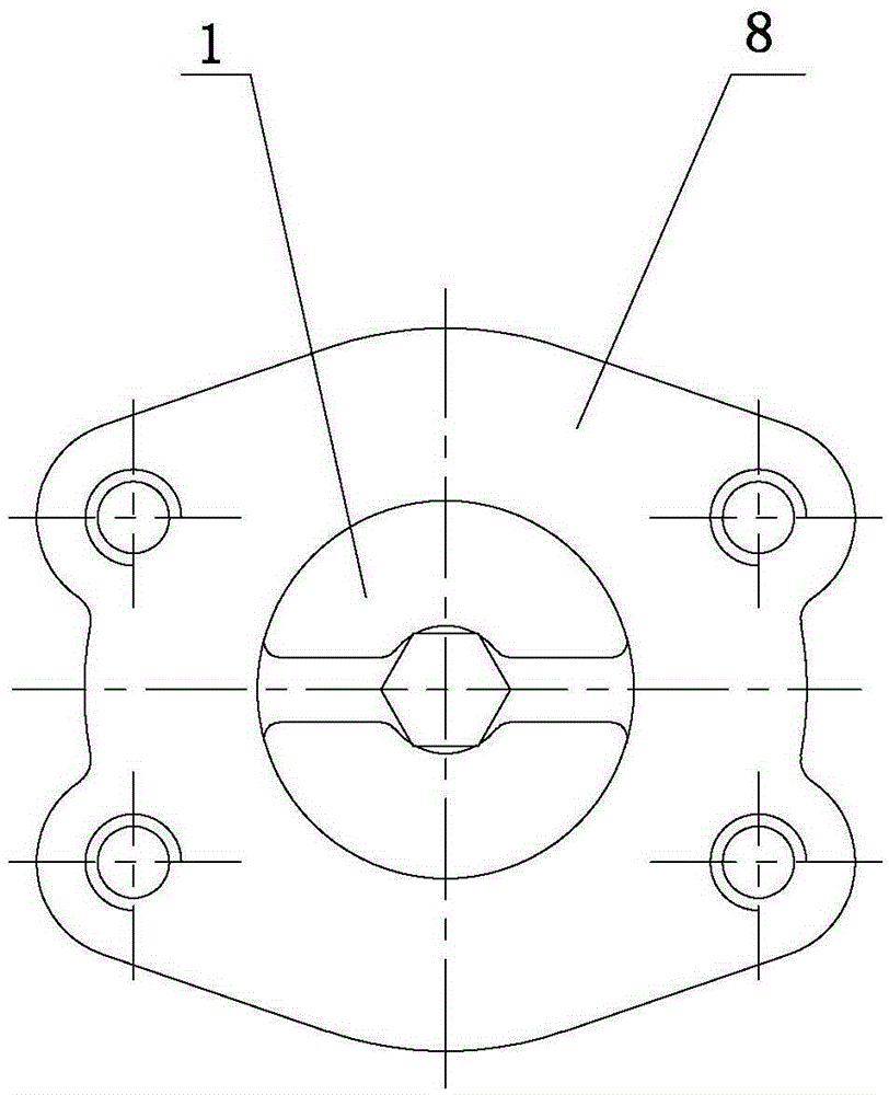
Figure 2
Abstract
Description
Technical field
[0001] The invention relates to a cooling system device in a hydraulic system of an engineering machinery, in particular to a one-way valve applied in a hydraulic system. Background technique
[0002] The hydraulic oil flow in the hydraulic system of construction machinery depends on the displacement of the pump, the number of revolutions of the engine, and the area ratio of the two ends of the cylinder. The number of revolutions of the engine varies with operation and varies greatly (1000 rpm ~ 2500 rpm), and The area ratio of the two ends of the cylinder is large, so the hydraulic oil flow rate changes greatly. The requirement of the cooler is that the flow rate is stable and the general flow rate configuration is small (considering the reduction of cost and installation location). At present, the cooling system in the hydraulic system of construction machinery uses a traditional one-way valve for diversion, due to the traditional one-way valve flow pressure La...
Examples
Embodiment Construction
[0012] The present invention will be further explained below in conjunction with the drawings:
[0013] Such as figure 1 , 2 As shown, the present invention includes a valve body 8 connected to a hydraulic system. One end of the valve body 8 is provided with an oil inlet 11, and the other end is provided with an oil outlet 1. The valve body 8 is provided with a cover plate 9 covering the oil inlet 11, a bolt 7 is installed in the center of the cover plate 9, and a spring 5 is sleeved on the bolt 7, and one end of the spring 5 rests on the cover plate (9). One end is installed outside the support tube 6 which is also sleeved on the bolt 7. At one end of the bolt 7 near the oil outlet 1, a pressure plate 4 for positioning the support tube 6 and an adjusting nut 3 for adjusting the pressure of the spring 5 on the cover plate 9 are provided. The adjusting nut 3 is also used to fix and adjust the opening pressure. A split pin 2 is provided at the end of the bolt 7 to prevent the adju...