
Stator loading and unloading device with fast knockout function
A function and stator technology, applied in the field of stator loading and unloading devices, can solve the problems of low placement efficiency, troublesome processing, and incorrect placement of stators and rotors, and achieve the effects of fast placement speed, convenient processing and production, and accurate placement positions.
Patent Information
- Authority / Receiving Office
- CN · China
- Patent Type
- Applications(China)
- Current Assignee / Owner
- Publication Date
- 2013-01-02
Smart Images
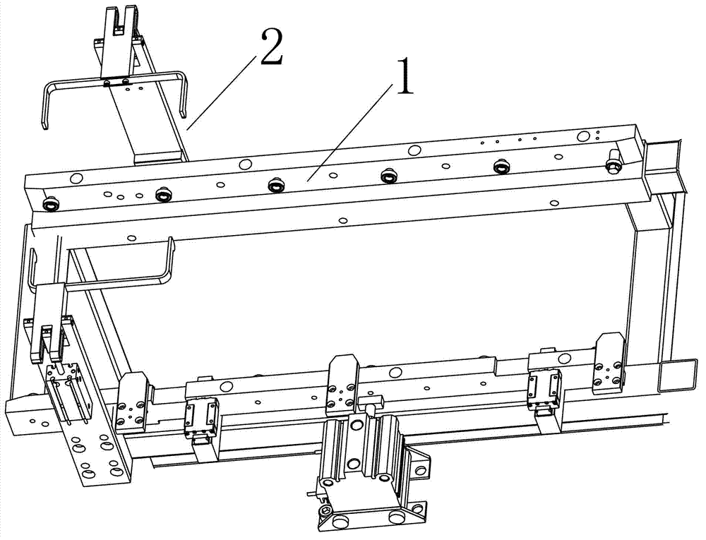
Figure 1 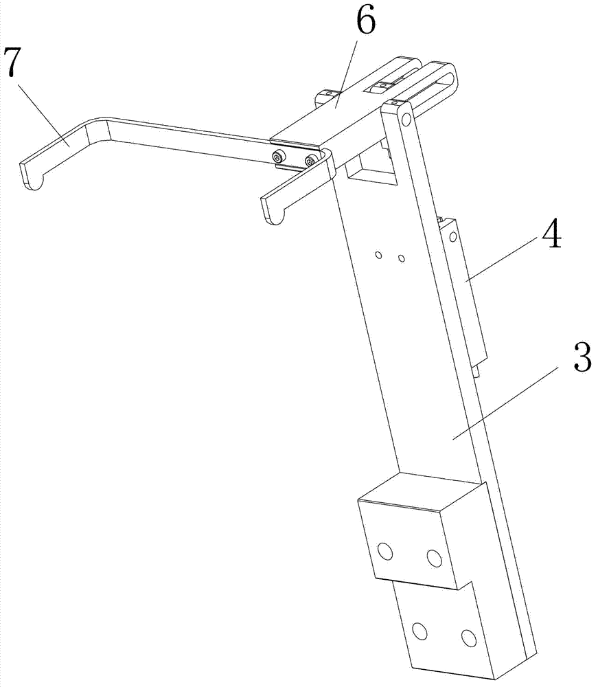
Figure 2 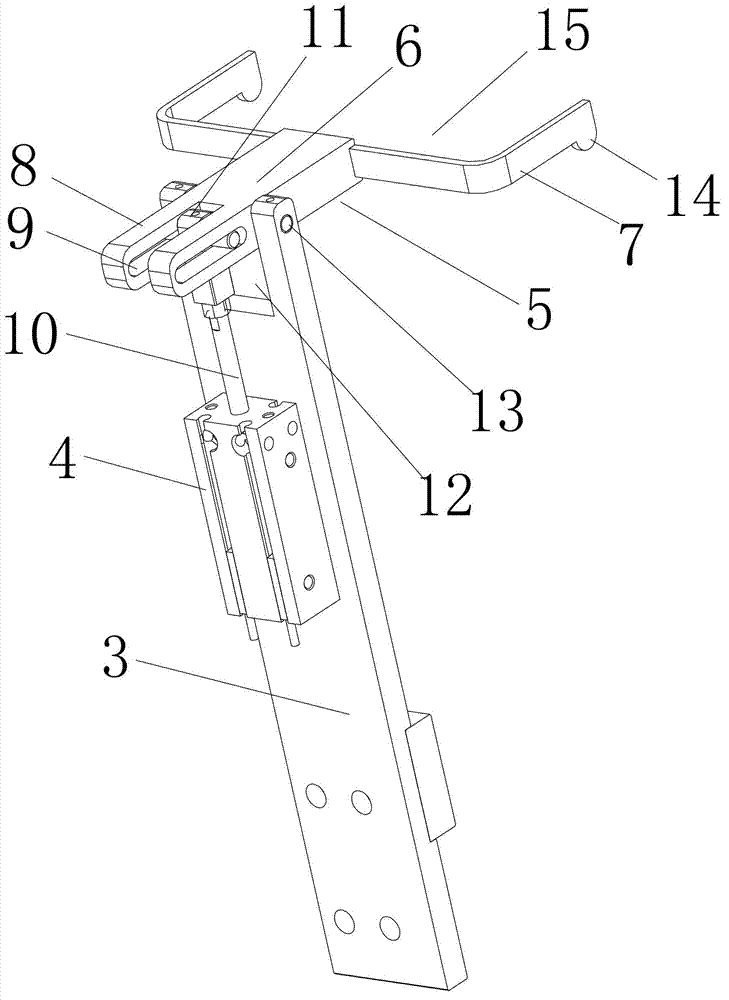
Figure 3
Abstract
Description
technical field
[0001] The invention relates to a stator loading and unloading device, in particular to a stator loading and unloading device with a fast feeding function. Background technique
[0002] The stator and the rotor are obtained by stamping the raw material disc through a punching machine, because the stator and the rotor are stamped by a raw material disc. The stator and rotor are adsorbed by adsorption equipment, and then placed in different filling mechanisms. At present, the stator and rotor are mostly placed manually. The speed of separating the rotor and the stator is slow, the placement efficiency is low, and it cannot keep up with the processing speed of the punching machine. Simultaneously, it is very easy to put the stator and the rotor into the wrong material holding mechanism, which brings great troubles to subsequent processing. Contents of the invention
[0003] In order to solve the problem of placing the stator and the rotor manually in the pri...
Examples
Embodiment Construction
[0016] The present invention will be further described below in conjunction with the accompanying drawings.
[0017] Such as Figure 1-3 As shown, a stator loading and unloading device with a fast feeding function includes a ring machine 1, an adsorption device, a material holding mechanism, and a feeding mechanism 2. The ring machine 1 is provided with a material holding mechanism. A feeding mechanism 2 is arranged beside it, and an adsorption device for placing materials to the feeding mechanism is arranged in the ring machine 1 .
[0018] The feeding mechanism 2 includes a support plate 3, a cylinder 4, and a feeding frame 5. The rear surface of the supporting plate 3 is provided with a cylinder 4, and the feeding frame 5 includes a rotating beam 6 and a feeding arm 7, respectively on both sides of the rotating beam 6 front end. A punching arm 7 is provided. The beating arm 7 can be an L-shaped beating arm, and the opening 15 formed by the two L-shaped beating arms faces ...