
A display panel and a display device having the display panel
A technology for a display panel and a display device, applied in static indicators, nonlinear optics, optics, etc., can solve the problems of the large width of the front case 401, the edge light leakage of the display device, and the small display area of the display device, etc. Film substrate, good visual effect, high promotion value effect
Patent Information
- Authority / Receiving Office
- CN · China
- Patent Type
- Patents(China)
- Current Assignee / Owner
- Publication Date
- 2015-09-02
Smart Images
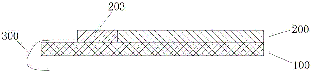
Figure 1 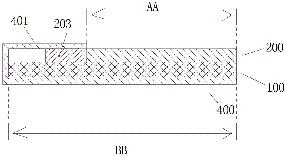
Figure 2 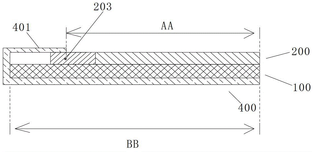
Figure 3
Abstract
Description
technical field
[0001] The present invention relates to the field of display technology, in particular to a display panel and a display device with the display panel. Background technique
[0002] Such as figure 1 As shown, it is a schematic structural diagram of an existing display panel. The display panel mainly includes an array substrate 100 for controlling the orientation of liquid crystals and a color filter substrate 200 for displaying images. It is connected with the main control circuit board used for controlling the display panel. The main control circuit board is in the prior art and has nothing to do with the invention point of the present invention, so it is not shown in the figure. Specifically, considering factors such as simplifying the processing technology, the existing flexible circuit board 300 is connected to the display panel by setting the array substrate 100 of the display panel to be larger than the color filter substrate 200, and the switch circuit...
Examples
Embodiment 1
[0045] Example 1 ( Figure 4a , 4b )
[0046]The display panel includes an array substrate 100 and a color filter substrate 200 , and a circuit connection unit 201 is provided on one or more sides of the color filter substrate 200 ; the circuit connection unit 201 protrudes from the edge of the array substrate 100 . This application provides a new display panel structure. The grown color filter substrate is used to lay out the input circuit 600 of the display panel, and then connects the drive circuit and the switch circuit of the array substrate 100 through the input circuit 600, so as to The drive signal sent by the drive circuit is transmitted to the switch circuit of the array substrate 100 to control the display of the color filter substrate 200. The drive circuit is preferably connected based on the flexible circuit board 300, and the color filter substrate 200 is the user's visible area AA. , which is longer than the structural design of the array substrate 100 and in...
Embodiment 2
[0048] Example 2 ( Figure 5a , 5b )
[0049] The display device includes a frame 400 and the display panel in Embodiment 1. The display device also includes components such as a polarizer, a backlight module, and a main control circuit board frame 400, wherein the polarizer is located on the color filter substrate 200, and the backlight module is located on the Below the array substrate 100 , the main control circuit board is connected to the input circuit 600 of the display panel through the flexible circuit board 300 , which are not shown in the above-mentioned components. The array substrate 100 in this structure is shorter than the color filter substrate 200, and the light emitted by the backlight module can be blocked by the circuit connection unit 201 to prevent light leakage. Therefore, when assembling the display device, no display The front case 401 of the device is used for shielding, that is, it can be set as a structure without a front case as shown in the figur...
Embodiment 3
[0050] Example 3 ( Figure 6 )
[0051] This embodiment is a further improvement on the display panel on the basis of embodiment 1. The features not described in embodiment 3 are the same as in embodiment 1. Of course, the display panel in embodiment 3 can also be used in the display panel shown in embodiment 2. display device. The display panel of this embodiment includes an array substrate 100 , a color filter substrate 200 and an optical film 500 , and the array substrate 100 , the color filter substrate 200 and the optical film 500 are laminated sequentially from bottom to top. Among them, a circuit connection unit 201 is provided on one or more sides of the color filter substrate 200 for arranging the input circuit 600; the circuit connection unit 201 protrudes from the edge of the array substrate 100 to realize the display device for installing the display panel. Realize borderless display effect. The color filter substrate 200 also includes a display unit 202 for dis...