
Pressure cooker with splashing preventing and oily water collecting functions
A pressure cooker and anti-splash technology, applied in the field of pressure cookers, can solve the problems of increasing the exhaust pressure of the pressure cooker, difficult to popularize and apply for safety in use, and unfavorable for the safe use of the pressure cooker, and achieves the effect of increasing heat energy loss.
Patent Information
- Authority / Receiving Office
- CN · China
- Patent Type
- Applications(China)
- Current Assignee / Owner
- Publication Date
- 2014-05-28
- Estimated Expiration
- Not applicable · inactive patent
Smart Images
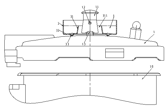
Figure 1 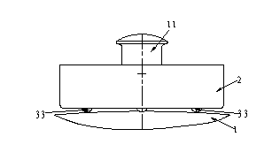
Figure 2 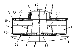
Figure 3
Abstract
Description
technical field
[0001] The invention relates to a pressure cooker for cooking, in particular to a pressure cooker with functions of preventing splash and collecting oil and water. Background technique
[0002] The cooking pressure cooker (hereinafter referred to as: pressure cooker) that the public uses on the gas range or induction cooker daily, for safety needs, the pot cover of pressure cooker is provided with gravity-type pressure-limiting exhaust valve (hereinafter referred to as: pressure-limiting valve). When the pressure cooker exhausts under pressure limitation, most of the gas is ejected from the four vent holes (hereinafter referred to as: cap holes) on the gravity cap (hereinafter referred to as: valve cap) of the pressure limiting valve, and the following inconveniences are prone to occur: 1. The hot gas mixed with oil, water and fine food particles (hereinafter collectively referred to as: mixed fluid) sprayed out along the horizontal direction is easy to splas...
Examples
Embodiment 1
[0028] The pressure cooker with the function of preventing splash and collecting oil and water according to Embodiment 1 of the present invention (for the structure see figure 1 , figure 2 and Figure 11 ), including a pot body 10 of a pressure cooker and a matching pot cover 1 with a pressure limiting valve, the pot cover 1 has a cylinder around the pressure limiting valve to block the mixed fluid sprayed from the pressure limiting valve Cover 2, its structure is characterized in that:
[0029] The lower part of the cylinder cover 2 is provided with a receiving groove 3 on the pot cover 1 surrounding the pressure limiting valve bonnet 11;
[0030] The above-mentioned receiving groove 3 is composed of the cylinder wall of the cylinder cover 2, the inner ring wall 31 with a through hole 311 located inside it, and the groove bottom 32 integrally connected between the bottom ends of the two;
[0031] The minimum aperture of the above-mentioned through hole 311 is greater than...
Embodiment 2
[0042] The pressure cooker with the function of preventing splash and collecting oil and water according to the second embodiment of the present invention (for the structure see Figure 3 to Figure 5 , Figure 11 and Figure 12 ). On the basis of Embodiment 1 of the present invention, Embodiment 2 is further constructed as follows, and its benefits are also described later, namely:
[0043] Further structure 1: the bottom of the groove 32 is provided with a sleeve shoulder 4 on the pot cover 1 surrounding the pressure limiting valve. The sleeve shoulder 4 is connected to the lower end of the pressure limiting valve sleeve 13 through the sleeve hole 41. The sleeve shoulder 4 There is a suitable distance between the bottom side of the bonnet 11 for the passage of the mixed fluid; the outer periphery of the sleeve shoulder 4 is located at the inner circumference of the bottom protrusion 33, and the sleeve shoulder 4 and the bottom protrusion 33 cooperate with each other so that...
Embodiment 3
[0050] The pressure cooker with the function of preventing splash and collecting oil and water according to the third embodiment of the present invention (for the structure see Figure 6 to Figure 8 , Figure 11 and Figure 12). On the basis of the second embodiment of the present invention, the third embodiment provides a practical limiting structure, that is, the inner circumference of the inner ring wall 31 is provided with a sleeve shoulder on the pot cover 1 that surrounds the pressure limiting valve. 4. The sleeve shoulder 4 is connected to the lower end of the pressure limiting valve sleeve 13 through the sleeve hole 41, and there is a suitable distance between the sleeve shoulder 4 and the bottom side of the valve cap 11 for the passage of the mixed fluid; the outer periphery of the sleeve shoulder 4 There are at least three protruding heads 42 that are evenly distributed along the circumference, and the protrusions 42 are located on the inner periphery of the inner ...