
Diaphragm stroke experimental device and method
An experimental device and experimental method technology, which is applied in the direction of pump testing, liquid displacement machinery, machine/engine, etc., can solve the problems of time-consuming and labor-intensive installation of diaphragms, increased production costs, and delays in construction schedules, so as to achieve simple operation methods and reduce experimental costs. Period, avoid damage effect
Patent Information
- Authority / Receiving Office
- CN · China
- Patent Type
- Applications(China)
- Current Assignee / Owner
- Publication Date
- 2015-02-25
Smart Images
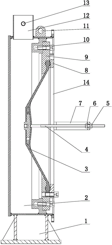
Figure 1
Abstract
Description
technical field
[0001] The invention belongs to the technical field of diaphragm pump experimental devices, and in particular relates to a diaphragm stroke experimental device and a test method. Background technique
[0002] The diaphragm chamber is the heart of the diaphragm pump. The diaphragm chamber separates the propellant oil from the slurry through the rubber diaphragm, avoiding the mixing of the propellant oil and the slurry, so that the moving parts such as the piston in the cylinder run in clean hydraulic oil, thus ensuring the piston and other components service life. Therefore, it is particularly important to detect whether the rubber diaphragm is damaged and whether the diaphragm is running in a reasonable position.
[0003] The rubber diaphragm is equipped with a guide rod with a magnetic ring, and together with the oil replenishment and discharge signal detection device installed on the oil cylinder, the diaphragm stroke detection device is formed, and the r...
Examples
Embodiment Construction
[0035] The diaphragm stroke experiment device of the present invention comprises a cavity 2, and is characterized in that: one side of the cavity 2 is an opening 14, and a support 10 is arranged in the cavity 2 corresponding to the opening 14; a liquid filling port 12 is arranged above the cavity 2 An overflow port 13 is provided on the side of the liquid filling port 12; a support frame 7 is provided outside the opening 14, and a screw rod 4 extending into the opening 14 is provided on the support frame 7, and the screw rod 4 passes through the first positioning in the support frame 7 The nut 6 and the second positioning nut 5 outside the support frame 7 are fixed on the support frame 7 .
[0036] As a preferred solution of the present invention, a base 1 is provided at the bottom of the cavity 2 , and a lifting ear 11 is provided above the cavity 2 .
[0037] As another preferred solution of the present invention, the support 10 is provided with a front pressing plate 8 and ...