
Multi-degree-of-freedom controllable parallel type mobile robot
A mobile robot and degree of freedom technology, applied in the field of robots, can solve the problems of poor positioning accuracy, low stiffness, and large required torque, and achieve the effect of small motion inertia of the mechanism, good dynamic performance, and reduced dynamic torque.
Patent Information
- Authority / Receiving Office
- CN · China
- Patent Type
- Applications(China)
- Current Assignee / Owner
- Publication Date
- 2015-04-01
- Estimated Expiration
- Not applicable · inactive patent
Smart Images
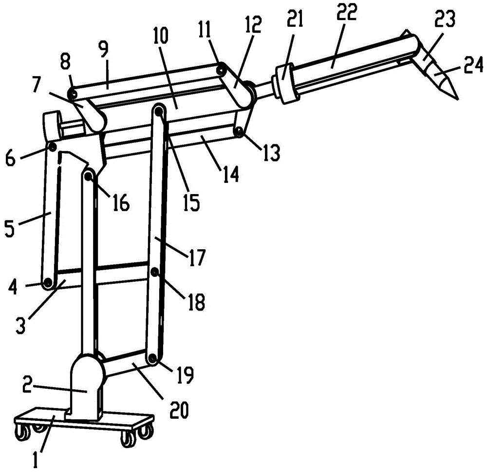
Figure 1 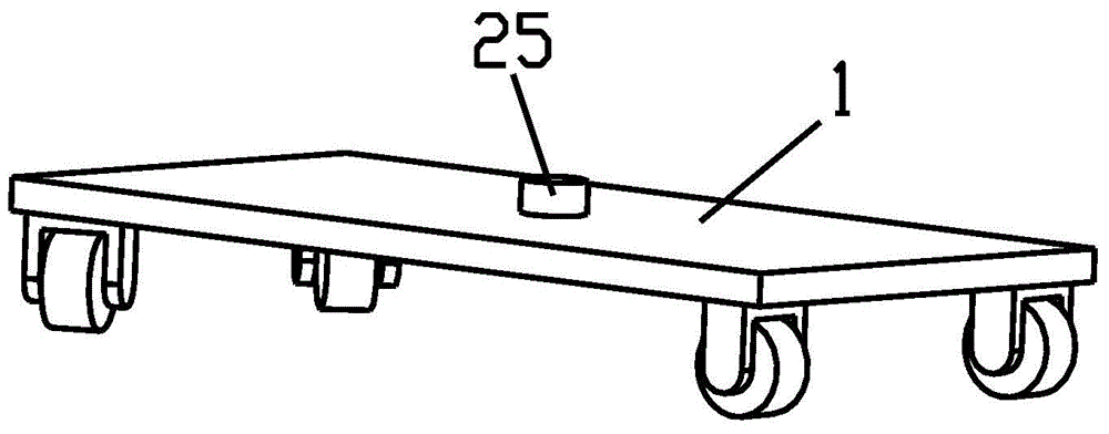
Figure 2 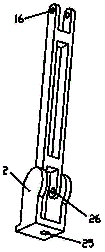
Figure 3
Abstract
Description
technical field
[0001] The invention relates to the field of robots, in particular to a multi-degree-of-freedom controllable parallel mobile robot. Background technique
[0002] The development and application of robot technology has greatly changed human production and life style. The use of robots can not only quickly and accurately complete boring repetitive tasks, but also safely and reliably complete many complex operations in dangerous and harsh environments, which can greatly reduce people's labor intensity, increase labor productivity, and improve product quality. As an advanced robot with a closed-chain structure, the parallel robot has the advantages of low motion inertia, strong load capacity, and high rigidity in terms of mechanism, which just makes up for the shortcomings of traditional industrial robots in these aspects, making parallel robots a potential robot. High-speed, high-precision motion platform. In the past 30 years, researchers have done a lot of r...
Examples
Embodiment Construction
[0025] The technical solutions of the present invention will be further described below in conjunction with the accompanying drawings and embodiments.
[0026] control figure 1 , figure 2 , image 3 , Figure 4 , Figure 5 , Image 6 , Figure 7 with Figure 8 , the multi-degree-of-freedom controllable parallel mobile robot described in the present invention includes a fuselage 2, a first connecting rod 20, a second connecting rod 17, a third connecting rod 3, a fourth connecting rod 5, a fifth connecting rod Rod 10, sixth connecting rod 7, seventh connecting rod 12, eighth connecting rod 9, ninth connecting rod 14, tenth connecting rod 21, eleventh connecting rod 22, twelfth connecting rod 23, end effector 24 and the movable platform 1, the specific structural diagram and connection method are: the fuselage 2 is connected to the movable platform 1 through the first rotating pair 25, and the fuselage 2 is connected to one end of the first connecting rod 20 through the ...