
Magnetic heat power generation device
A technology of magnetothermal power generation and hard magnetism, which is applied in the direction of thermoelectric devices, generators/motors, and electrical components that utilize thermal changes in magnetic permeability, can solve problems such as unreasonable structures, and achieve improved adjustability and improved assembly Efficiency and structural stability, the effect of changing the accuracy of the dwelling station
Patent Information
- Authority / Receiving Office
- CN · China
- Patent Type
- Applications(China)
- Current Assignee / Owner
- Publication Date
- 2015-04-22
Smart Images
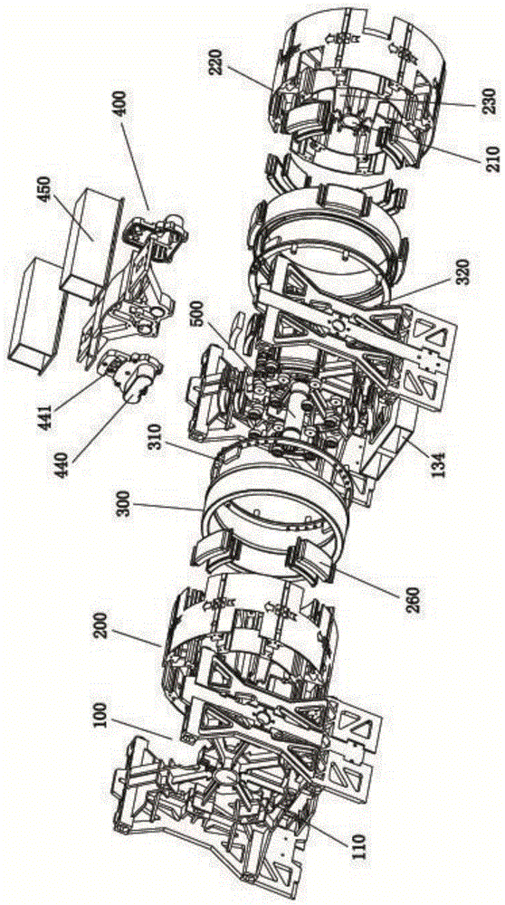
Figure 1 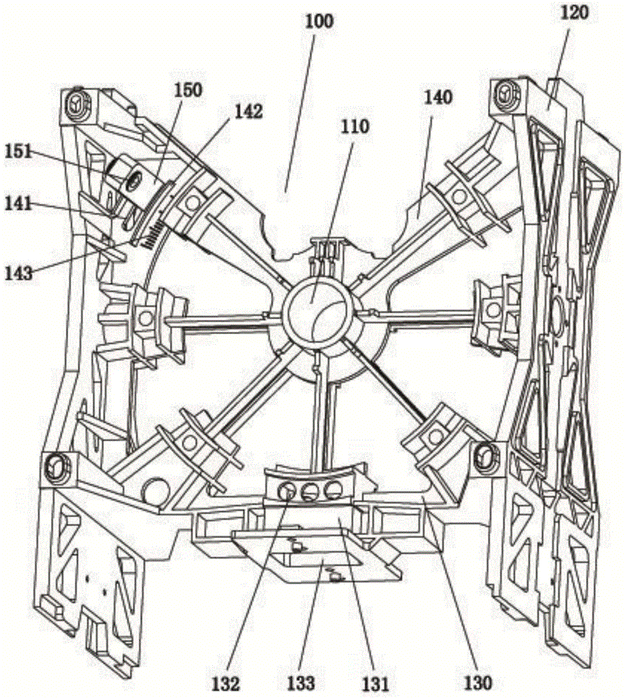
Figure 2 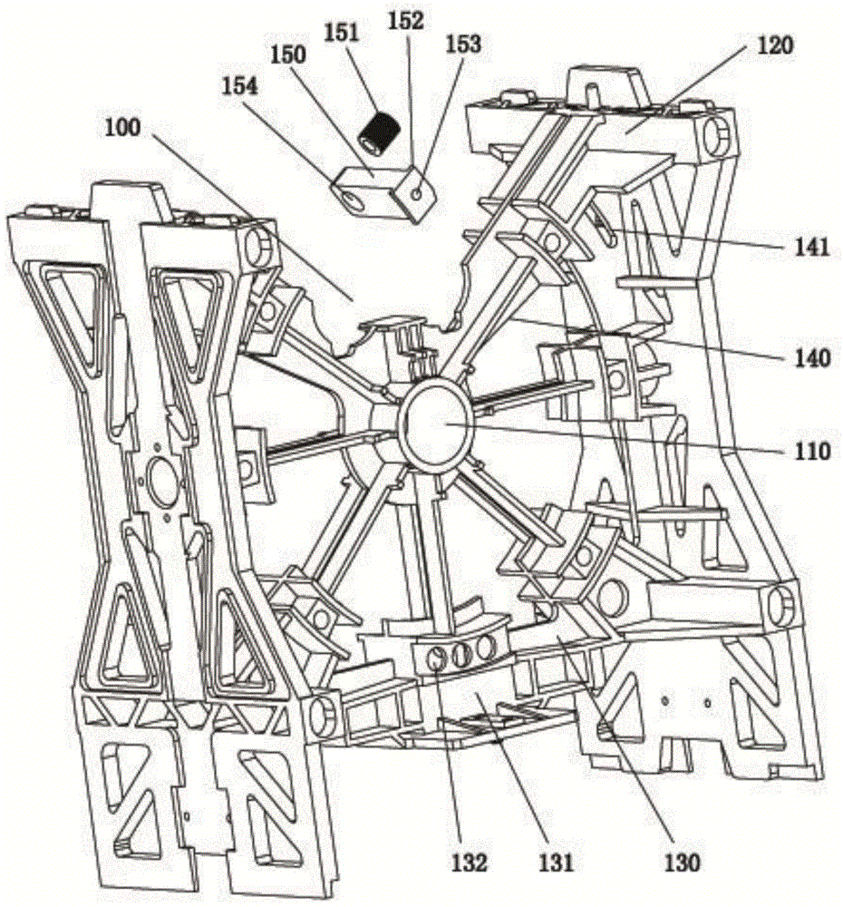
Figure 3
Abstract
Description
technical field
[0001] The invention relates to the technical field of magnetocaloric engines, in particular to a magnetocaloric power generation device. Background technique
[0002] The magnetothermal power generation device is a thermal energy utilization device that converts thermal energy into magnetic energy, and then converts the magnetic energy into mechanical energy to generate power. It generally includes a stator equipped with soft magnets, a rotor equipped with hard magnets, and soft magnetic heating and heating in the stator. Cooling heating cooling system.
[0003] Existing magnetocaloric power generation devices have unreasonable structural settings, which are specifically manifested in the following aspects: 1. In the heating and cooling system, the heating device and the cooling device respectively heat and cool the soft magnets, the structure is large in volume, the pipeline is complicated, and the integrated The temperature is low, and the heating and coo...
Examples
Embodiment Construction
[0030] The present invention will be described in further detail below in conjunction with the accompanying drawings, but the embodiments of the present invention are not limited thereto.
[0031] Such as figure 1 As shown, a magneto-caloric power generation device according to the present invention includes at least one magneto-caloric power generation unit, and the magneto-caloric power generation unit includes two main supports 100, a rotor 200, a stator 300 and a heating and cooling device 400 that are connected and arranged correspondingly. , the main support 100 is provided with a shaft seat A110, and the rotor 200 is provided with a shaft seat B210, an accommodation space is formed between the two main supports 100, the rotor 200 is located in the accommodation space, and the power shaft 500 passes through two The axle seat A110 and the axle seat B210 are arranged so that the rotor 200 is rotatably arranged in the accommodation space, the two stators 300 are fixedly arr...