
Anti-interference pulse signal conditioner
A pulse signal and conditioner technology, which is applied in the field of signal conditioners, can solve the problems of poor anti-interference and restrict the development of pulse signal instruments, and achieve the effects of suppressing high-frequency interference, eliminating bias voltage, and simple circuit structure
Patent Information
- Authority / Receiving Office
- CN · China
- Patent Type
- Applications(China)
- Current Assignee / Owner
- Publication Date
- 2015-05-13
- Estimated Expiration
- Not applicable · inactive patent
Smart Images
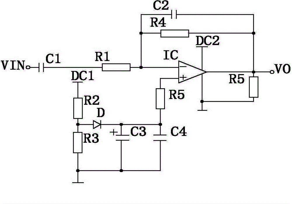
Figure 1
Abstract
Description
technical field
[0001] The invention relates to a signal conditioner, in particular to an anti-interference pulse signal conditioner. Background technique
[0002] In the diagnosis of traditional Chinese medicine in my country, through pulse diagnosis, doctors can have a general understanding of the patient's physical condition, and then prescribe the right medicine. The pulse signal can directly reflect part of the condition of the patient's heart. We can understand the ups and downs of qi and blood in the patient's viscera. With the development of science and technology, there are more and more pulse signal instruments. Nowadays, pulse signal conditioners generally have complex structures and poor anti-interference performance, which restricts the development of pulse signal instruments. Contents of the invention
[0003] The object of the present invention is to provide an anti-interference pulse signal conditioner in order to solve the above problems.
[0004] The pres...
Examples
Embodiment Construction
[0010] The present invention will be further described below in conjunction with accompanying drawing:
[0011] Such as figure 1 As shown, the present invention includes a first capacitor C1, a second capacitor C2, a third capacitor C3, a fourth capacitor C4, a first resistor R1, a second resistor R2, a third resistor R3, a fourth resistor R4, and a fifth resistor R5 , diode D, the first power supply DC1, the second power supply DC2 and the amplifier IC, the first power supply DC1 and the second power supply DC2 are DC power supplies, the third capacitor C3 is a polar capacitor, the first terminal of the first capacitor C1 and the signal The input terminal VIN is connected, the second end of the first capacitor C1 is connected to the first end of the first resistor R1, and the second end of the first resistor R1 is simultaneously connected to the first end of the second capacitor C2 and the first end of the fourth resistor R4. terminal is connected to the inverting input term...