
Gas-solid mixing conveying device capable of achieving even distribution and application of gas-solid mixing conveying device
A technology of uniform distribution and conveying device, applied in the direction of pipes/pipe joints/pipe fittings, mechanical equipment, pipe components, etc., can solve the problems of affecting the airflow distribution of the channel and increasing the flow resistance, and achieve a small resistance loss and a simple overall structure. Effect
Patent Information
- Authority / Receiving Office
- CN · China
- Patent Type
- Applications(China)
- Current Assignee / Owner
- Publication Date
- 2015-11-25
- Estimated Expiration
- Not applicable · inactive patent
Smart Images
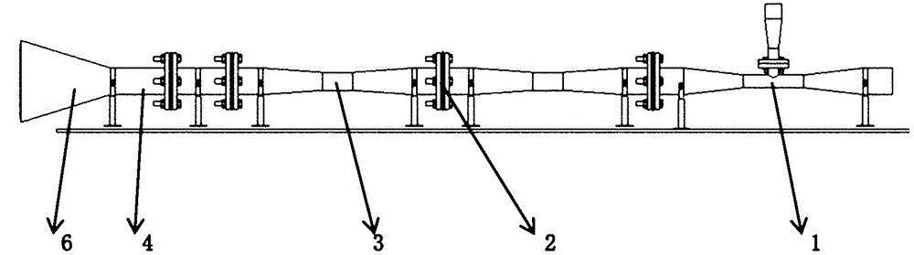
Figure 1 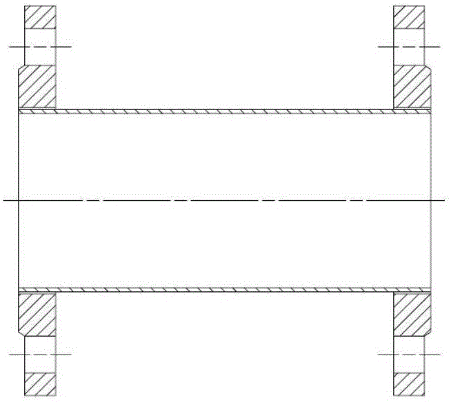
Figure 2 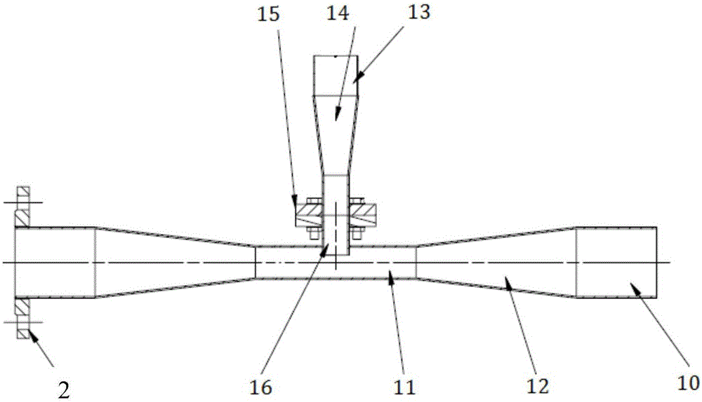
Figure 3
Abstract
Description
technical field
[0001] The invention relates to a gas-solid mixing conveying device capable of realizing uniform distribution and its application. Background technique
[0002] At the inlet of the engine, in order to prevent the entry of dust, leaves, grass roots, stones and even birds in the air, blocking devices, such as partitions and mesh covers, are usually added to separate large particles. For small particles, a guide device can be added at the inlet of the engine, and the inertia can be used to separate the solid particles in the airflow. separated into the bifurcated channel).
[0003] The performance test of inertial particle separator is an effective measure to verify its gas-solid separation. In the test, the inlet environment of the inertial particle separator needs to create uniformly distributed sand and dust inlet conditions, so it is necessary to configure a gas-solid (gas solid particle) mixing device that can achieve uniform distribution.
[0004] Exist...
Examples
Embodiment Construction
[0034] The present invention will be described in detail below in conjunction with specific embodiments. The following examples will help those skilled in the art to further understand the present invention, but do not limit the present invention in any form. It should be noted that those skilled in the art can make several modifications and improvements without departing from the concept of the present invention. These all belong to the protection scope of the present invention.
[0035] An embodiment of the gas-solid mixing conveying device that can realize uniform distribution provided by the present invention is figure 1 As shown, it mainly includes the lower sand section 1, the expansion section 3, the rectification section 4, and the expansion section pipeline (annular expansion nozzle) 6 located at the outlet, and flanges 2 are used to connect each part.
[0036] According to the aerodynamic parameters (aerodynamic parameters, such as pressure, speed, temperature, etc...