
Indexable thread machining blade
A technology for thread machining and inserts, applied in the field of indexable thread inserts, can solve the problems of difficult cast iron materials for inserts, difficult to curl and break, and reduce cutting edge strength, etc., to achieve heat dissipation, reliable processing, and reduced contact area effect
Patent Information
- Authority / Receiving Office
- CN · China
- Patent Type
- Applications(China)
- Current Assignee / Owner
- Publication Date
- 2016-02-03
Smart Images
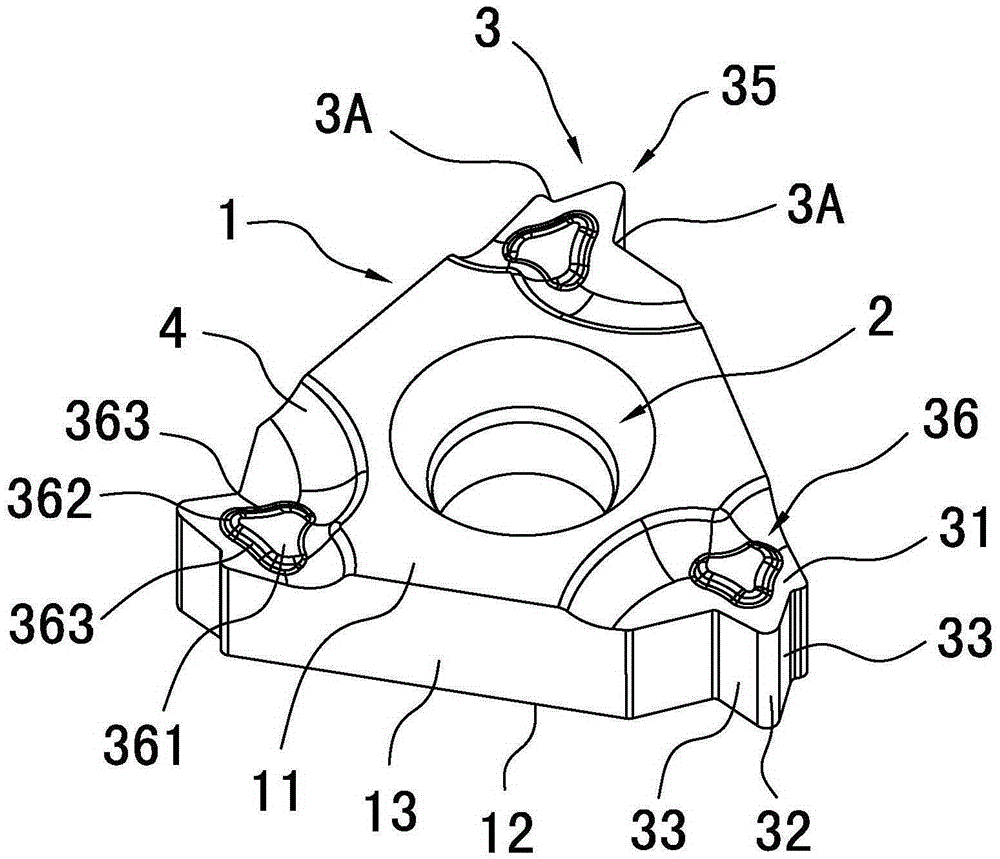
Figure 1 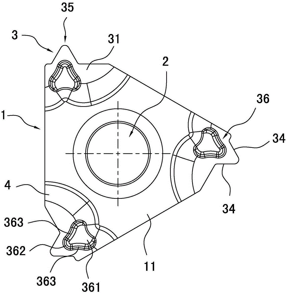
Figure 2 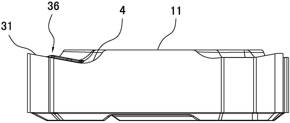
Figure 3
Abstract
Description
technical field
[0001] The invention relates to the technical field of metal cutting tools, in particular to an indexable thread insert for thread processing. Background technique
[0002] Thread turning is an indispensable part of machining, and its main features are large feed per revolution and small depth of cut per cut, which requires the insert to have excellent wear resistance and chipping resistance.
[0003] In thread processing, there are mainly three feeding methods, namely radial feeding, lateral feeding and alternating feeding. Using different feeding methods will have different effects on chip shape, thread quality and tool wear. Impact, in practical applications, more radial feed is used. The thread is processed through multiple passes, and the cutting depth of each cutting is gradually reduced. In the first half stage, due to the large cutting depth of each cutting, the chips generated are thicker and narrower. In the half stage, especially when the thread ...
Examples
Embodiment
[0029] Such as Figure 1 to Figure 5 As shown, in an indexable threading insert of the present invention, the insert body 1 is surrounded by an upper surface 11, a lower surface 12, and a side surface 13, and is in the shape of an approximately equilateral triangular flat plate, at the center of the upper surface 11 and the lower surface 12. There is a blade center hole 2 along the thickness direction of the blade and through the blade body 1. The blade body 1 is also provided with a cutting edge portion 3. There are three cutting edge portions 3. The cutting edge portion 3 consists of a rake face 31, a round edge The arc surface 32, two bevel sides 33 and the lower surface 12 are enclosed, and the two bevel sides 33 intersect with the rake face 31 to form two side cutting edges 34, which are connected with the rear ends of the two side cutting edges. Edge 3A, the angle between two side cutting edges 34 is the cutting edge angle 35, and the rake face 31 sinks gradually from th...