
Roller support reciprocated driving device for high-speed cold pilger mill
A reciprocating driving device, cold rolling mill technology, applied in the direction of the driving device for metal rolling mills, metal rolling, metal rolling, etc., can solve the problem that the speed of rolling tubes is difficult to achieve, the production capacity of steel tubes cannot be obtained, and the reciprocation of partial waste roll stands Movement speed and other issues to achieve the effect of improving rolling capacity
Patent Information
- Authority / Receiving Office
- CN · China
- Patent Type
- Applications(China)
- Current Assignee / Owner
- Publication Date
- 2016-08-10
Smart Images
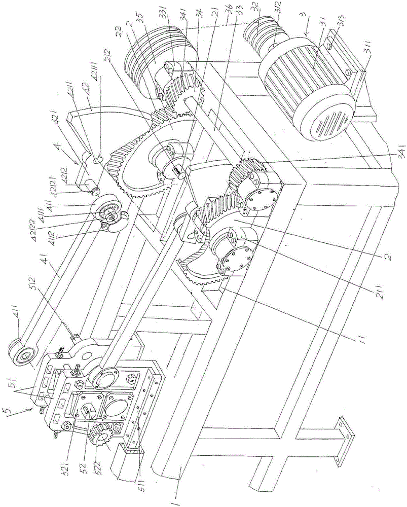
Figure 1
Abstract
Description
technical field
[0001] The invention belongs to the technical field of steel pipe rolling machinery, and in particular relates to a reciprocating driving device of a roll stand of a high-speed cold-rolling pipe mill. Background technique
[0002] Cold rolling mill is a special equipment for cold rolling by using perforated tubes (also known as capillary tubes or blank tubes), because of its excellent blanking performance and the ability to roll non-ferrous metal seamless tubes with good viscosity, The high material utilization rate and the surface roughness are significantly better than those of cold drawn pipes, so they are widely used in the steel pipe manufacturing industry.
[0003] As known in the industry, a complete set of pipe rolling mills usually includes a conveying device, a feeding device (such as patents CN102059261B, CN10343300B), a steel pipe rotating device (such as CN103433305B, CN104107835A), a rolling device and an output device. The rolling device mainl...
Examples
Embodiment Construction
[0020] In order to facilitate a clearer understanding of the technical essence and beneficial effects of the present invention, the applicant will describe in detail below by way of examples, but the description of the examples is not intended to limit the solution of the present invention, and any Equivalent transformations that are only formal but not substantial should be regarded as the scope of the technical solutions of the present invention.
[0021] See figure 1 , shows a frame 1 with a frame-like structure; a pair of large gears 2 are rotatably supported on the right end of the frame 1 through a large gear half shaft 21 in a state corresponding to each other; a large gear drive mechanism 3 is shown , the large gear drive mechanism 3 is arranged on the frame 1 at a position corresponding to the right side of the aforementioned pair of large gears 2 and is in driving cooperation with the pair of large gears 2; a pair of connected A lever mechanism 4, the pair of link m...