

Machining equipment with working clearance convenient to adjust
A working gap and machining technology, applied in metal processing equipment, metal processing mechanical parts, metal processing, etc., can solve the problems of heavy processing head, influence of push-pull drive accuracy, complex workload, etc., to achieve reliable operation and avoid size Changes, the effect of ensuring the accuracy of the drive
Patent Information
- Authority / Receiving Office
- CN · China
- Current Assignee / Owner
- Publication Date
- 2016-08-10
Smart Images
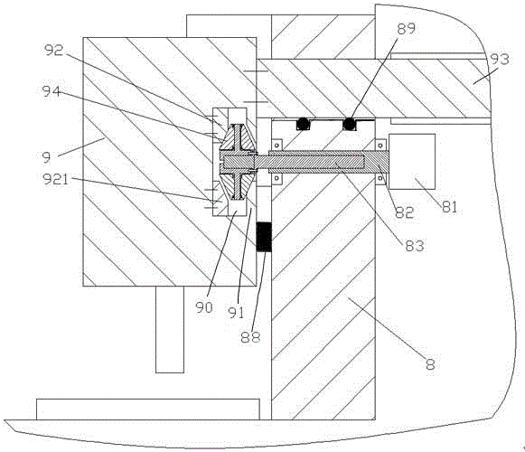
Figure 1 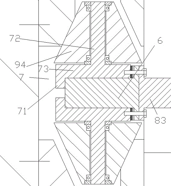
Figure 2 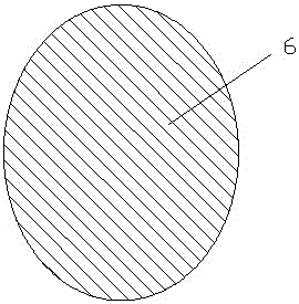
Figure 3
Abstract
Description
technical field
[0001] The invention relates to the field of processing devices, in particular to a mechanical processing device for conveniently adjusting the working gap. Background technique
[0002] There is a wide range of needs for back-and-forth and lateral drives of machine heads. In some existing devices, orthogonal drive systems are often superimposed on each other, that is, one drive is the main drive, and the other auxiliary drive is located within the main drive. This way is easy to cause the processing head to be too heavy. However, although the push-pull drive of the rollers can be used to implement the auxiliary drive, the weight of the drive system need not be applied to the processing head, but the gap between the rollers and the processing head often affects the precision of the push-pull drive. Adjusting the gap often brings complicated workload. Contents of the invention
[0003] The object of the present invention is to provide a machining equipmen...
Examples
Embodiment Construction
[0009] Combine below Figure 1-3 The present invention will be described in detail.
[0010] According to an embodiment of the present invention, a machining device for conveniently adjusting the working gap includes a frame 8 and a processing head 9 mounted on the frame 8 capable of reciprocating movement in the front-rear direction, in the processing head 9 A chute cavity 90 extending in the front-rear direction is provided, and the chute cavity 90 is used to roll and cooperate with the roller pusher so as to be pushed and pulled by the roller pusher to adjust the left-right direction perpendicular to the front-rear direction. position, wherein the roller pusher includes a threaded sleeve member 82 rotatably mounted on the frame 8 for threaded engagement with a threaded moving rod 83, and the threaded sleeve member 82 is driven to rotate by a drive motor 81, The thread moving rod 83 is detachably fixedly connected with a push head having two conical section roller assemblie...