
Double-sided laminator driving mechanism
A driving mechanism and laminating machine technology, which is applied in the directions of packaging machines, packaging, transportation and packaging, etc., can solve the problems of lower production efficiency, double-sided machine cardboard creases, degumming, etc., to overcome cardboard creases and degumming, extend Effects of service life and maintenance cost reduction
Patent Information
- Authority / Receiving Office
- CN · China
- Patent Type
- Applications(China)
- Current Assignee / Owner
- Publication Date
- 2016-08-10
- Estimated Expiration
- Not applicable · inactive patent
Smart Images
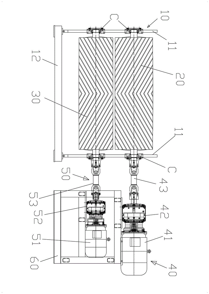
Figure 1 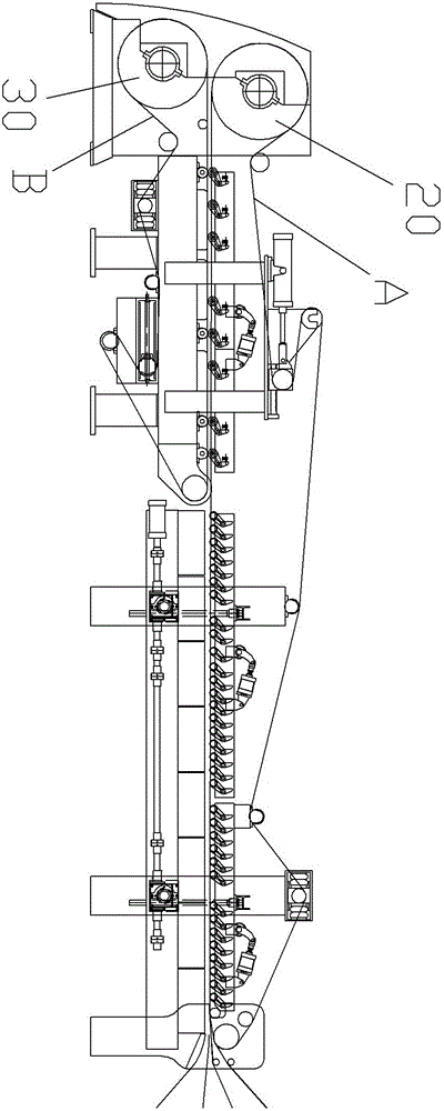
Figure 2
Abstract
Description
technical field
[0001] The invention relates to a double-sided laminating machine, more specifically, to a driving mechanism of a double-sided laminating machine. Background technique
[0002] The traditional double-sided machine driving mechanism is a single motor through a belt or gear reduction mechanism to separate two output ends connected to the upper and lower rubber wheels for transmission. After the rubber wheel and the conveyor belt are worn out, the speed deviation of the upper and lower conveyor belts will increase, which will cause creases and degumming of the cardboard of the double-sided machine. Since the transmission speed ratio of the upper and lower rubber wheels of the traditional double-sided machine driving mechanism is fixed, the out-of-synchronization problem can only be solved by repairing the rubber wheels and replacing the conveyor belt, which reduces the production efficiency. Contents of the invention
[0003] The main purpose of the present i...
Examples
Embodiment Construction
[0013] Such as Figure 1 to Figure 2 Shown is a preferred specific implementation example of the present invention, a double-sided laminating machine drive mechanism, including a frame 10, a rubber wheel 20 rotatably installed in the frame 10, a rotatably mounted The lower rubber wheel 30 located below the upper rubber wheel 10 in the frame 10, the first power mechanism 40 for driving the upper rubber wheel 20 to rotate and the lower rubber wheel for driving the The second power mechanism 50 that the wheel 30 rotates drives the upper rubber wheel 10 and the lower rubber wheel 20 through the first power mechanism 30 and the second power mechanism 50 to control the speed synchronously, so that the upper rubber wheel 20 is driven The upper conveyor belt A and the lower conveyor belt B driven by the lower rubber wheel 20 realize synchronous operation.
[0014] Further, the shaft heads at the left and right ends of the upper rubber wheel 20 and the lower rubber wheel 30 are instal...