
Waste utility pole removal machine
A technology for removal of electric poles, which is applied in the field of waste electric pole removal machines, can solve the problems of affecting the access of surrounding vehicles, exposed steel bars of electric poles, potential safety hazards, etc., and achieves rapid and efficient movement, increased mobility, and easy transportation Effect
Patent Information
- Authority / Receiving Office
- CN · China
- Patent Type
- Patents(China)
- Current Assignee / Owner
- Publication Date
- 2017-12-29
Smart Images
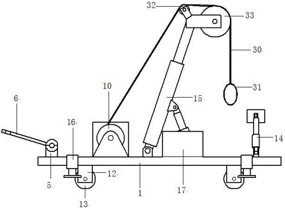
Figure 1 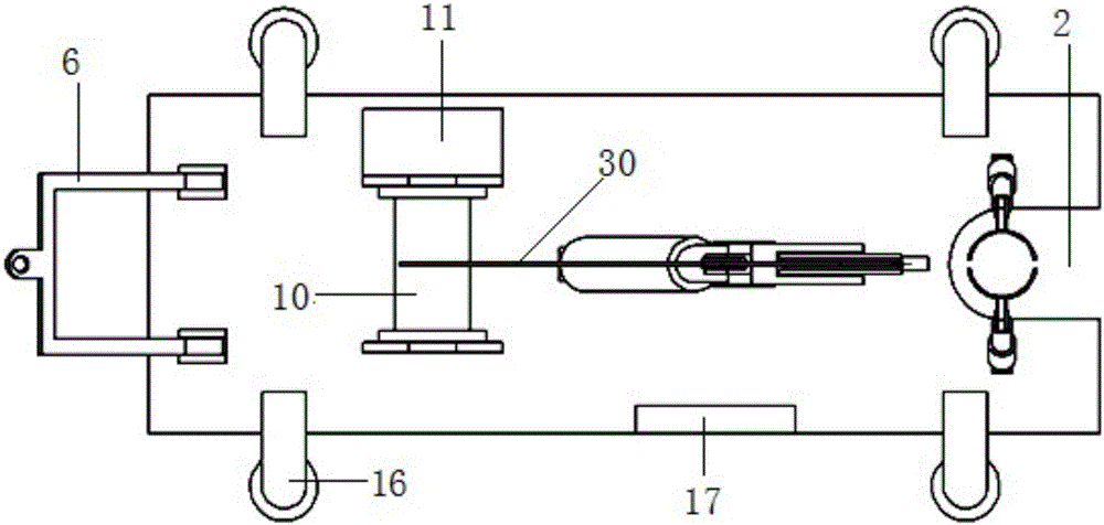
Figure 2 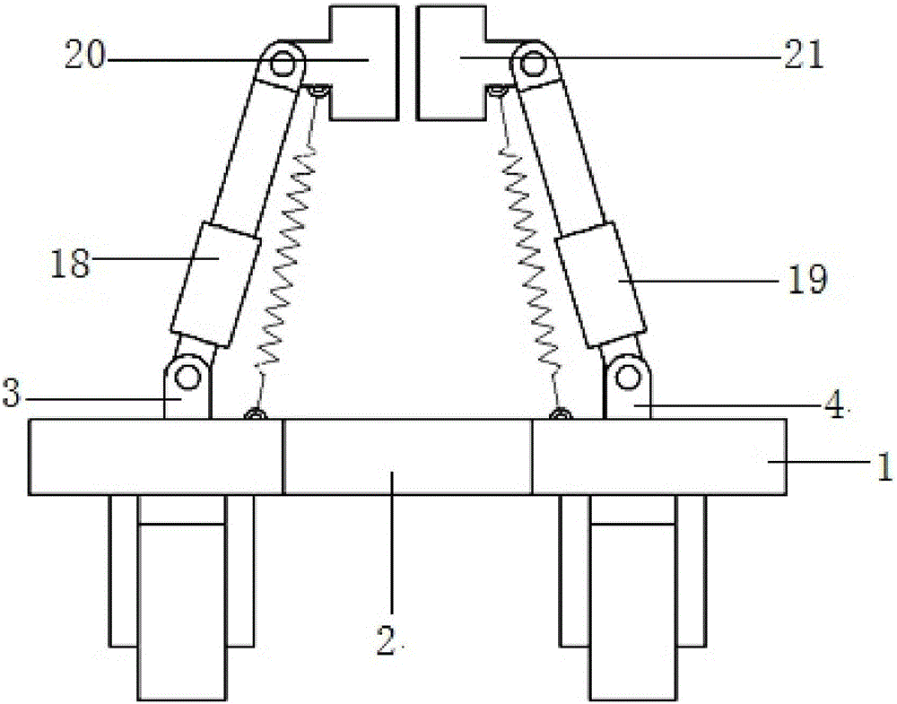
Figure 3
Abstract
Description
technical field
[0001] The invention relates to a machine for removing waste and old utility poles, and relates to the technical field of electric power construction equipment. Background technique
[0002] As the foundation of national economic development, electricity is the basis for the development of the national economy. Power grid security and power supply reliability are already important guarantees for the lives of the masses and social development, and power facilities are the carriers for the stable production, transportation and supply of electric energy. Therefore, the work of power facilities is of great significance. However, due to road construction, wire upgrade, transformer box transfer and other reasons, some abandoned utility poles often appear in various places. The environment is incompatible, and it also affects the access of surrounding vehicles, which brings a lot of inconvenience to the surrounding people. Some utility poles have been around for a ...
Examples
specific Embodiment approach
[0018] Specific implementation method: combined Figure 1-6 As shown, including base plate 1, a U-shaped groove 2 is opened on one side of the length direction of the base plate 1; A base 3 and B base 4 are symmetrically installed on both sides of the upper surface of the base plate 1 U-shaped groove 2; A base 3, B base 4 A pull-up device 14 is connected through a pin shaft; a C base 5 is installed on the side opposite to the U-shaped groove 2 on the upper surface of the base plate 1; the C base 5 is connected with a traction frame 6 through a pin shaft; the U-shaped groove 2 on the upper surface of the base plate 1 D base 7, E base 8, F base 9 are installed between C base 5; D base 7 is connected with reel 10 through pin shaft; D base 7 side is installed with motor 11 on the bottom plate 1 upper surface width direction; The machine shaft of 11 is splinedly connected with reel 10; E base 8, F base 9 are connected with hoisting device 15 by pin shaft; Base plate 1 lower surface...