
Hydraulic valve dedicated to windlass
A hydraulic valve and windlass technology, applied in the field of hydraulic valves, can solve the problems of affecting the surrounding working environment, easy oil leakage at the joints, scattered installation of components, etc., and achieves the effects of complete functions, low production costs, and saving installation space
Patent Information
- Authority / Receiving Office
- CN · China
- Patent Type
- Applications(China)
- Current Assignee / Owner
- Publication Date
- 2016-10-26
- Estimated Expiration
- Not applicable · inactive patent
Smart Images
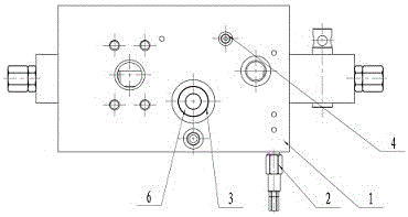
Figure 1 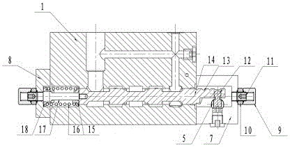
Figure 2 
Figure 3
Abstract
Description
Technical field:
[0001] The invention relates to a hydraulic valve, in particular to a special hydraulic valve for windlass. Background technique:
[0002] As we all know, hydraulic transmission technology is widely used in industrial and civil industries due to its large transmission force, flexible control, easy transmission and configuration. With the continuous development of hydraulic technology and the development trend of ships, hydraulic technology is more widely used in the field of ships, and The existing marine windlass control valve block includes a main valve block and a spool installed in it, a relief valve, a pressure compensation valve, a three-way shuttle valve, two fixed throttle plugs, a cut-off plug, a return spring, Operating mechanism, etc., but these parts are relatively scattered when installed, and the combination takes up more space. At the same time, the joints of these combined parts are prone to oil leakage, thereby affecting the surrounding work...
Examples
Embodiment Construction
[0014] like figure 1 and figure 2 As shown, this specific embodiment adopts the following technical solutions: a special hydraulic valve for windlass, including a main valve body 1, a relief valve 2, a diverter valve core 3, a shuttle valve 4, an operating shaft 5, a spring 6, an end cover 17, end cover 2 8, cap nut 9, nut 10, limit screw 11, ball pin 12, valve core 13, connecting rod 14, spring seat 15, spring 2 16, pull rod 17 and spring seat 2 18 ; The main valve body 1 is provided with a relief valve 2, a shuttle valve 4, a diverter valve core 3 and a spring 6; the end cover 1 7 is fixedly connected to the lower right side of the main valve body 1; the end cover 2 8 is fixedly connected to the lower left side of the main valve body 1; there are two limit screw rods 11, and the limit screw rods 11 are fixedly connected to the outer sides of end cap one 7 and end cap two 8 through cap nut 9 and nut 10 respectively Central; the spool 13 is movably connected inside the lowe...